Page 8
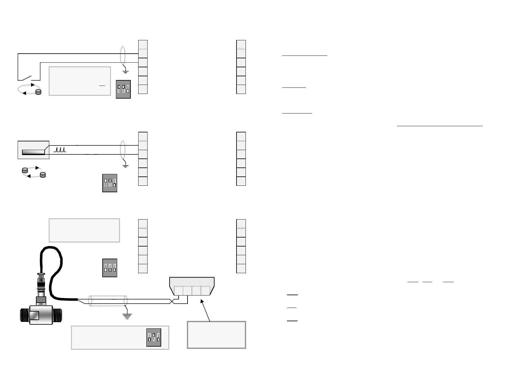
3.2 Flowmeter connections ( unpowered sensors )
Page 13
4.9 Presetting power levels
When the instrument is operated without external power being applied a special “Power
Mode ” program option will appear at level 12 of the programming chart. The three power
modes enable maximisation of the battery life according to operational requirements:
Ultra Power Save:
Typically selected if reading the register infrequently. Has the effect of
greatly extending the battery life.
In operation the display scrolls a prompt “PRESS ANY KEY ” when key
is pressed display wakes up for 4 minutes then returns to sleep mode*.
Standby :
Display becomes active whenever a key is pressed or product flows
through the flowmeter. Display returns to sleep mode* after 4 minutes of
no flow input or key actions, prompt then returns to “PRESS ANY KEY ”.
Continuous:
Display is active at all times resulting in reduced battery life.
* In sleep mode (and programming mode) flow is always continually totalised.
5. ADDITIONAL PROGRAM PARAMETERS ( model RT12 )
5.1 Analog Output
The loop powered 4 ~ 20mA output can be spanned anywhere within a flow range.
Testing the current loop can be done during programming when 4mA will output when at
programming level L14 and 20mA will output at programming level L15 (page 16).
5.2 Flow Alarms
Two flow alarm FET transistor relays may be programmed for Low & High flow alarms.
5.3 Flow Alarm Deadband
Alarms are NPN/PNP link selectable 100 milliamp max. An adjustable deadband (reset
differential) provides a trip buffer zone about the set point in order to overcome alarm
“chattering ” when the flow rate is fluctuating close to the alarm set point.
Deadband is entered as % of each set point value (refer to page 16 for an example).
5.4 Dual Flow Inputs
When externally powered the RT12 accepts inputs from two flowmeters (input A & input B), a
separate scaling factor is entered for the second flow input, the instrument is then
programmed for one of the dual input functions of A+B
, A-B or A÷B (ratio).
A+B
Both inputs are added and displayed as one for Rate & Totals.
A-B
Input B is subtracted from input A & the difference is displayed for both Rate & Totals.
A÷B
Totalises A & B separately & Rate is a function of A÷B to give instantaneous ratio.
Note : - When using A & B inputs the functions of Scaled Pulse output, Alarm set points
and the Analog output are relevant to resultant computation between A & B.
- The analog output of function A÷B can be used as an input for ratio control.
2. Voltage Pulse
S
N
0.1 ~ 2 vdc
Yellow
Green
6
5
4
3
2
7
8
9
10
11
High flow alarm
Low flow alarm
Scaled pulse output
Remote reset
+ 8~24VDC supply
- 4~20mA output
+ 4~20mA output
Flow input B
Flow input A
-0V Ground
121
-0V Ground + 8~24VDC supply
ON
1 2 3
1. Reed Switch
For reed switch inputs DIP
switch 1 (noise & bounce
filter) & 2 should be on
[ 200hz max. frequency ]
6
5
4
3
2
7
8
9
10
11
High flow alarm
Low flow alarm
Scaled pulse output
Remote reset
+ 8~24VDC supply
- 4~20mA output
+ 4~20mA output
Flow input B
Flow input A
-0V Ground
121
-0V Ground + 8~24VDC supply
ON
1 2 3
Default setting for input B if
input B is not being used.
ON
1 2 3
3. Coils
Typically turbine flowmeters
& coil style
paddle wheel flow sensors
Coil inputs A & B
A
A
B B
6
5
4
3
2
7
8
9
10
11
High flow alarm
Low flow alarm
Scaled pulse output
Remote reset
+ 8~24VDC supply
- 4~20mA output
+ 4~20mA output
Flow input B
Flow input A
-0V Ground
121
-0V Ground + 8~24VDC supply
ON
1 2 3
Twisted pair
Note: Coil input board
must be removed if
using flow inputs at
terminals 3 or 4
Ground screen