Page 16
6. PROGRAMMING FLOW CHART
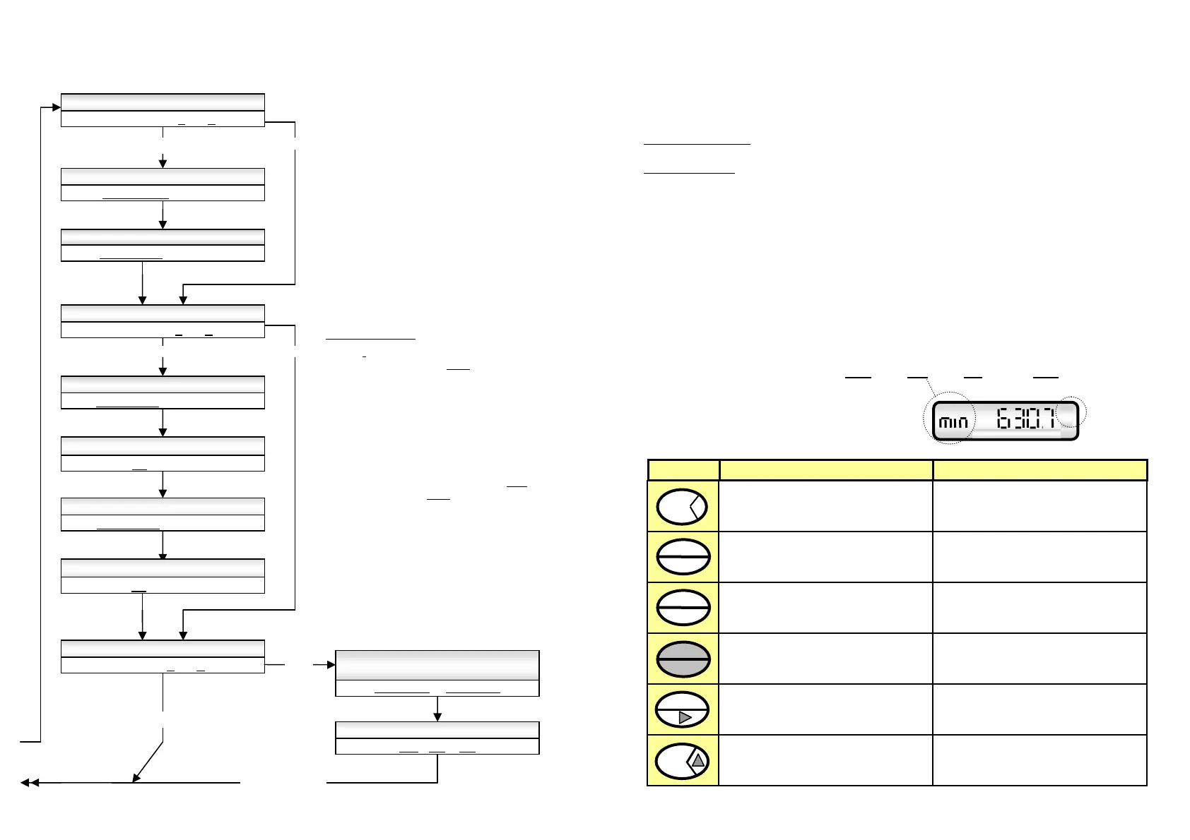
6.2 Program levels 13~23 ( Model RT12 only )
Page 5
2. OPERATION
2.1 Accumulative Total
Accumulative total can be reset at L2 in the program mode. The accumulative total can be
displayed momentarily or continuously through use of the front panel ACCUM TOTAL key.
Momentary display
: Accumulative total is displayed only whilst the key is held pressed.
Latching display
: To have the accum. total display latch when key is pressed simply
press & hold the ACCUM TOTAL key for 10 seconds, the ACCUM
TOTAL display will then latch each time the key is pressed.
Holding the accumulative total key again for 10 seconds will revert
this key function back to a momentary action.
2.2 Resettable Total ( also see pages 10 & 18 for remote reset feature )
The display toggles between Rate & Total when the RATE-TOTAL key is pressed.
Pressing the RESET key whilst displaying total will cause the total to reset to zero.
2.3 Rate display
When rate is displayed the leading three alpha characters on the left of the display “flash ”
with the time base for rate eg. rate /SEC
. rate /min. rate /HR. or rate /DAY. Decimal points
float to provide good resolution & rangeability.
2.4 Keypad functions
Lt
RATE
Ltr / min
YES
L13 ANALOG OUTPUT REQUIRED Y / N
4 ~ 20mA Y / N
L14 ENTER FLOW RATE AT 4mA
XXXXX.XXX LOW
L15 ENTER FLOW RATE AT 20mA
XXXXX.XXX HIGH
program return
YES
L16 ALARM OUTPUTS REQUIRED Y / N
ALARMS Y / N
L23 SET DUAL INPUT FUNCTION
A+B A-B A/B
L22 ENTER NUMBER PULSES PER
Ltr m3 kg gal lb (unit) FOR INPUT B
K0000.001 - K999999.9
1) Low flow alarm occurs when the flow falls
below the low set point, High
flow alarm occurs
when the flow goes above the high set point.
2) Deadband (Reset Differential), provides a
buffer zone about the alarm set point in order
to avoid alarm output “chattering ” on & off
when the flow rate is hovering about an alarm
set point.
The % deadband applies above the Low
set
point and below the High
set point. Deadband
is set as a percentage of each set point.
Eg: 5% deadband at a low alarm set point of
100 L/hr will cause a low alarm when the
flow drops to 100 L/hr, the alarm will
switch off when the flow increases beyond
105 L/hr.
Alarm outputs
L21 DUAL INPUTS REQUIRED Y / N
DUAL Y / N
L17 ENTER FLOW RATE LOW ALARM
XXXXX.XXX LOW
L19 ENTER FLOW RATE HIGH ALARM
XXXXX.XXX HIGH
L18 ENTER LOW ALARM DEADBAND %
BAND XX % LOW
L20 ENTER HIGH ALARM DEADBAND %
BAND XX % HIGH
YES
NO
NO
NO
Toggles between Rate & Total displays.
Resets the the Total display to zero
only when Total is being displayed.
No function
No function
1. Displays model & software revision No.
2. Pressing the Prog. & Rate/Total keys for 5
seconds enters you into the program mode
.
1. Each press steps you through each level of
the program chart.
2. Holding for 3 seconds fast tracks to the END
of the program from any program level.
No function
Selects the digit to be set, the selected digit
will be “flashing ” indicating that it can be
incremented.
No function
Increments the selected digit each time
that it is pressed.
KEY FUNCTION IN OPERATING MODE FUNCTION IN PROGRAM MODE
Displays Accumulative Total when pressed.
( refer clause 2.1 for options )
No function
ACCUM
TOTAL
RATE
TOTAL
RESET
PROGRAM
ENTER