8
3.0 ELECTRICAL CONNECTIONS
3.1 Instrument cable
Twisted multi-core low capacitance shielded instrument cable (22 AWG ~ 7x30)
should be used for electrical connection between the flow meter and the remote
instrumentation. The screen should be earthed at the readout instrument end
only to protect the transmitted signal from mutual inductive interference.
The cable should not be run in a common conduit or parallel with power and high
inductive load carrying cables as power surges may induce erroneous noise
transients onto the transmitted pulse signal or cause damage to the electronics.
Run the cable in separate conduit or with other low energy instrument cables.
3.2 Pulse output selection
Each flow meter has two independent pulse output signals that are linearly
proportional to volumetric flow. Pulse transmission can be up to 1000 metres
providing that wiring runs are in accordance with good wiring practices (see 3.1).
Reed switch :
A voltage free contact closure output providing a regular frequency ideally suited
for frequency to analog conversion & instantaneous flow rate indication. The
Reed Switch is also used for integrating and batching applications & is
connected into an approved intrinsically safe barrier when used in hazardous
locations. Maximum load is 24Vdc, 50mA limited by an integral 500ohm current
limiting resistor included in series with the reed switch.
Hall Effect sensor :
A high resolution, solid state, 3 wire NPN open collector requiring 5~24 Vdc
(20mA max.), produces a pre-shaped and amplified square wave more suited to
small volume batching applications requiring high levels of repeatability. The
square wave pulses are unevenly spaced due to the cyclic motion of the piston
but like the reed switch each pulse is representative of an equal volume.
Pulse output resolution :
Each flow meter is individually calibrated and supplied with a calibration
certificate showing the number of pulses per unit volume for the Hall sensor and
the reed switch outputs. Nominal figures are shown below.
Model No. Hall Sensor Reed Switch
Reed Switch 2
( pulses / USgal ) ( pulses / USgal ) ( Optional )
MP015 400 PPL (1520) 200 PPL ( 760 ) 400 PPL (1520)
MP025 100 PPL ( 380 ) 20 PPL ( 76 ) -
MP040 44 PPL ( 166 ) 7.3 PPL ( 28 ) -
MP050 20 PPL ( 76 ) 2.5 PPL ( 9.5 ) -
5
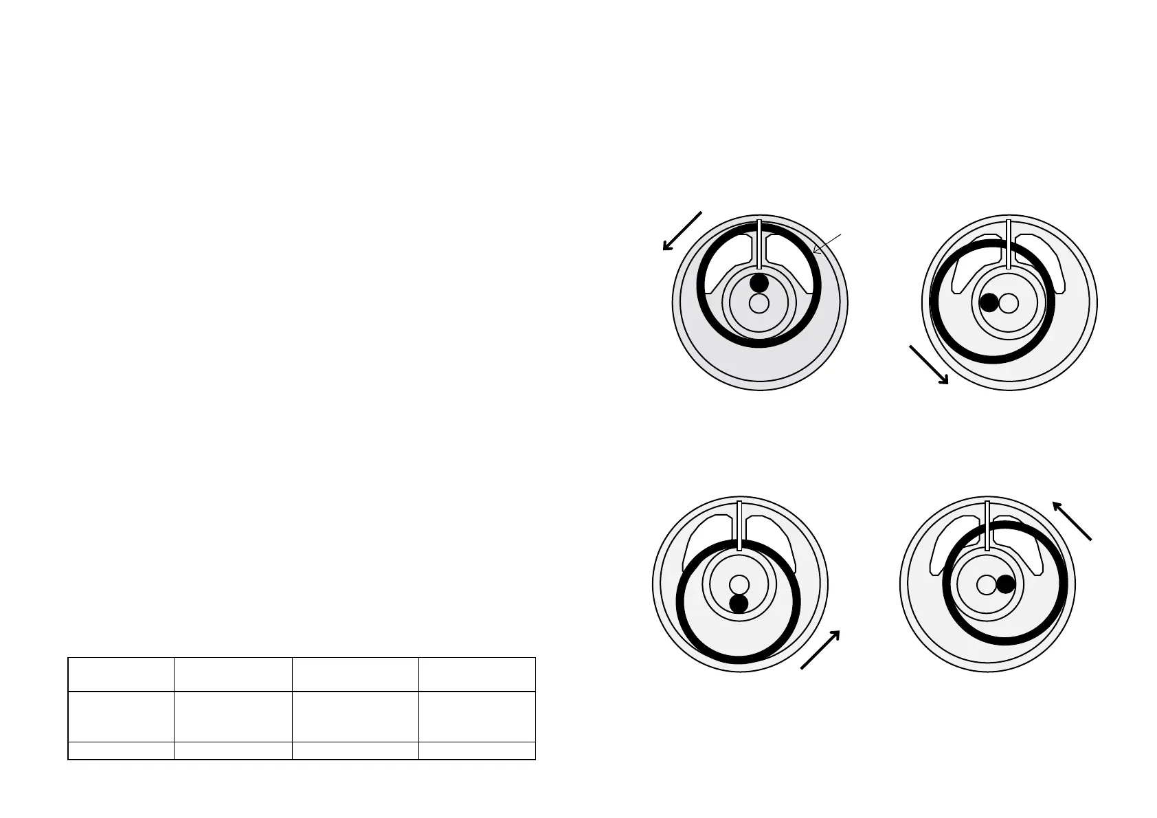
1.3 OPERATING PRINCIPLE
The Multipulse flow meter utilises the oscillating piston principle, where the
passage of liquid causes a piston to oscillate smoothly in a circular motion
inside a round measuring chamber. Each piston cycle displaces a known
volume of liquid from the inlet port to the outlet port. Small high energy
magnets located within the piston activate the integral electronics which in
turn generate high resolution pulse outputs suitable for remote flow integration
instruments, computers and PLC's .
1) The liquid flows through inlet A into 2) The volume outside the piston, to
the inner area of the piston causing the right, is displaced and exits
the piston to move in the direction through the opening B. Liquid also
of the arrow. flows through the inlet A into the
left- hand outer area.
3) The inner area of the piston is 4) The volume within the piston
completely cut off. The liquid flowing flows through the outlet B.
through A into the outer area moves
the piston further.
B A
Piston
B
A
B
A
B
A