Installation and Commissioning:
To install the Unit, proceed the following instruction:
1.
Push the unit into the panel and mount using the clamps provided.
2.
Connect the Auxiliary supply (80-270 VAC) to the terminals marked P and N.
3.
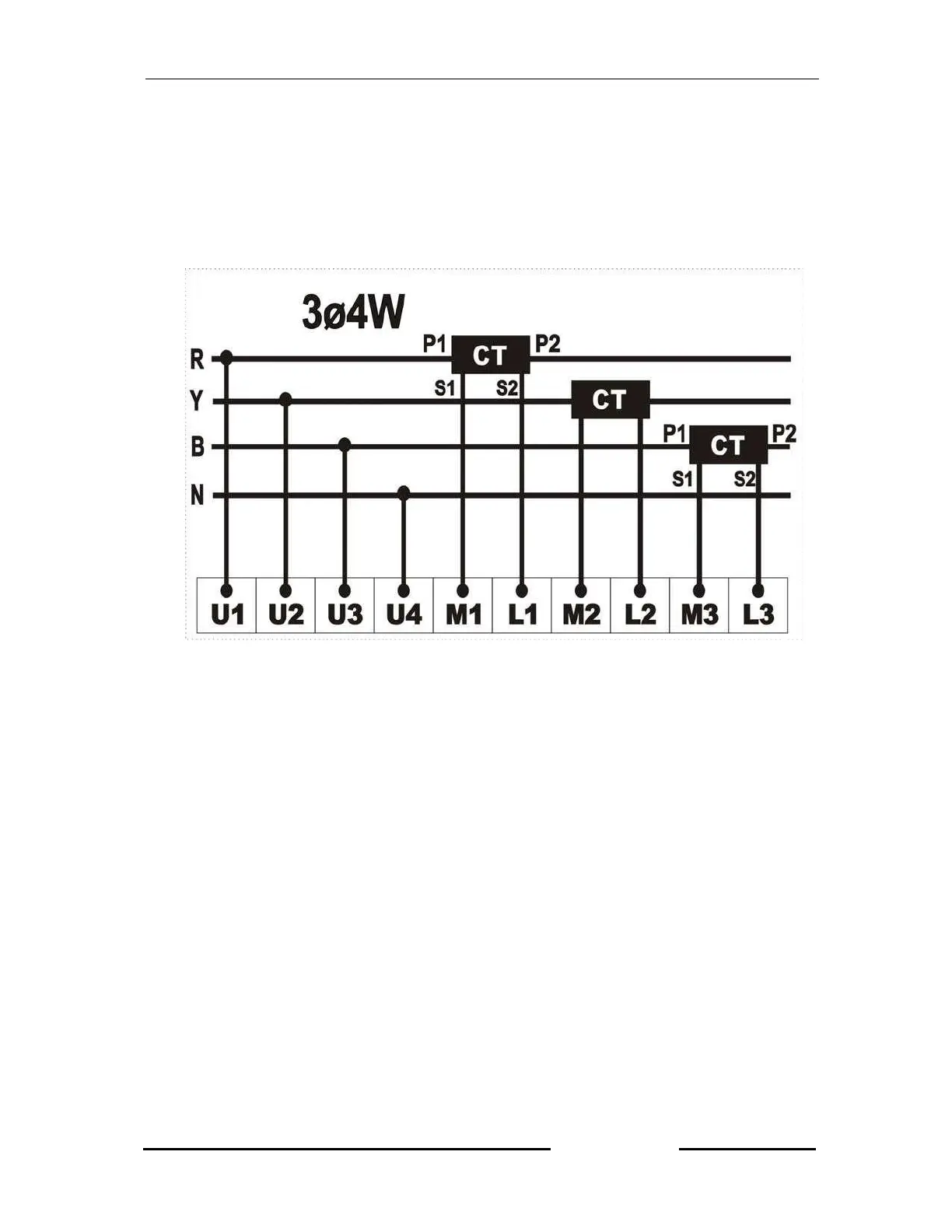
Connect the three phases with the phase sequence being R, Y, B to the
terminals marked U1, U2, and U3 respectively and then, connect the neutral
wire to the terminal marked, U4. Make sure the three phases coming to the unit
come through control fuse of 1.0A rating. This will protect the electronic inside
from damage due to sever overvoltage or phase fault in the system.
4.
Connect the two wires from R-phase CT to the terminals marked M1 and L1
such that S1 goes to the terminal marked M1. Connect the two wires coming
from the Y-phase CT to the terminals marked M2 and L2 such that S1 from the
CT goes to terminal marked M2. Connect the two wires coming from B-phase
CT to the terminals marked M3 and L3 such that S1 from the CT goes to the
terminals marked M3.
5.
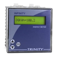
Supply power to the three phases. The unit will display power receiving
information such as ““---TRINITY----”,CT Ratio, Device Id(Only In the KWh
variant)” then it comes into Run Mode.
6.
First the CT-primary should be set, and then enters into Run Mode. Refer
Operational Details in the next section.
7.
Now the unit is ready for operation.