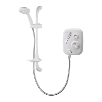
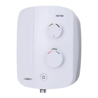
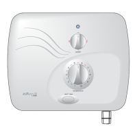
Aquasensation AS2000X
13
RESISTANCE IS FELT, DO NOT FORCE THE
CONTROL FURTHER.
Note: The temperature control rotates less than
one complete turn (fig.22). DO NOT force it
beyond these limits.
To stop the water flow, switch off the electricity
supply at the isolating switch.
Check for leaks in the pipework and remedy
if necessary. If rear entry has been used then
seal around pipes with mastic to prevent the
possibility of water entering the wall cavity.
DO NOT use plaster as this could cause difficulty
if maintenance is required later.
Setup procedure
MAKE SURE THE ELECTRICITY TO THE UNIT IS
SWITCHED OFF.
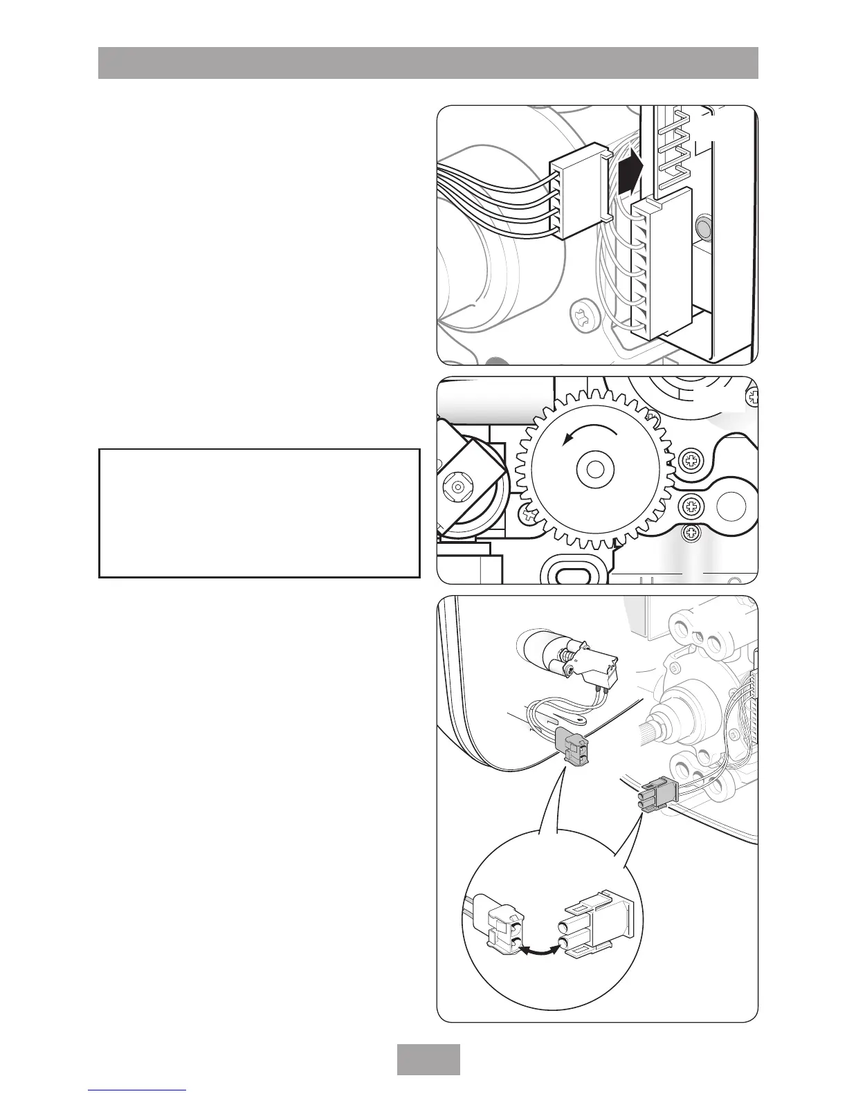
Pull off the temperature control. Remove the
commissioning link from the PCB (fig.23) and
store safely for future use.
Inside the cover, attached to the flow control
potentiometer is a 4-wire lead. Fit the connector
on the end of this lead to the 4 pins on the PCB
(fig.24) – it can fit either way.
Make sure the potentiometer control is rotated
fully anti-clockwise (fig.25).
Replacing the cover
Offer the cover to the backplate unit. Inside
the cover, attached to the stop/start switch is
a two wire lead. The socket on the end of this
lead must connect to the plug attached to the
backplate unit (fig.26).
Fit the cover, making sure the connector is fitted
to the PCB and the wires are clear of obstructions.
Secure with the top and bottom fixing screws
(fig.8).
WARNING!
Once the unit has been commissioned,
turn off the electricity supply at
the mains before removing the
commissioning link.
Fig.24
Fig.25
Fig.26