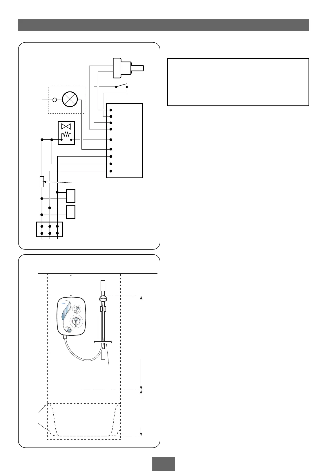
Shower can
be mounted
either side of
the riser rail
Spill-over
level
Ceiling
Use soap dish
retaining ring
Height of
sprayhead
and shower
to suit user’s
requirement
Shower unit
must not be
within an area
1 metre
from base
Space for cover
screw access
Fig.5
Siting
6
SITING OF THE SHOWER
IMPORTANT: If fitting to a tiled wall, always
mount the unit on the surface of the tiles.
NEVER tile up to the unit.
Refer to fig.5 for correct siting of the shower.
Position the unit vertically where it will NOT be
in direct contact with water from the sprayhead.
Note: Allow sufficient room between the ceiling
and the shower unit to access the top cover
screw.
Position the shower and sprayhead on the wall
so that all controls can be comfortably reached
when using the shower.
The sprayhead and riser rail can be positioned
either side of the shower unit.
Note: Water Regulations require the sprayhead
be ‘constrained by a fixed or sliding attachment
so that it can only discharge water at a point not
less than 25mm above the spill-over level of the
relevant bath, shower tray or other fixed
appliance’. The use of the supplied soap dish will
in most cases meet this requirement, but if the
sprayhead can be placed within a bath, basin or
shower tray, then a device must be fitted to
prevent back-flow.
L E N
Potentiometer
Switch
Solenoid
Motor
Capacitor 2
RFI suppression coil
Capacitor 1
PCB
Thermal
fuse
Fig.4 (schematic view )
WARNING!
The shower must not be positioned
where it will be subject to freezing
conditions.