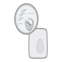
Fig.1
KEY TO MAIN COMPONENTS
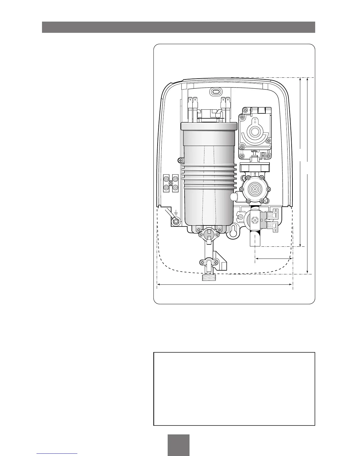
Inside unit (fig.1)
1 Top cable/pipe entry
2 Wall screw fixings
3 Cover screw fixings
4 Thermal safety cut-out (main)
5 Power selector assembly
6 Can and element assembly
7 Pressure switch assembly
8 Stabilising valve
9 Terminal block
10 Earth connection
11 Solenoid valve
12 Water inlet
13 Outlet temperature limiter
14 Pressure relief device (PRD)
15 Shower outlet
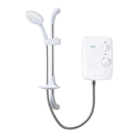
Pack contents
Shower unit
Sprayhead
Riser rail kit and fittings
Soap dish
Flexible hose
Screw fixing kit
Instructions, guarantee, etc.
To ensure the product suitability for commercial and
multiple installations, please contact Triton’s
specification advisory service prior to installation.
Telephone: (024) 7632 5491
Facsimile: (024) 7632 4564
E mail: technical@triton.plc.uk
NOTE: Not all wires have been depicted for
reason of clarity.
 Loading...