ASSEMBLY STEPS
1. PREPARATION
• Before assembling make sure that you will have enough space around the item.
• Use the supplied parts and hardware for the assembly.
• Before assembling please check whether all the required parts have been supplied as per the exploded
drawing on the previous page.
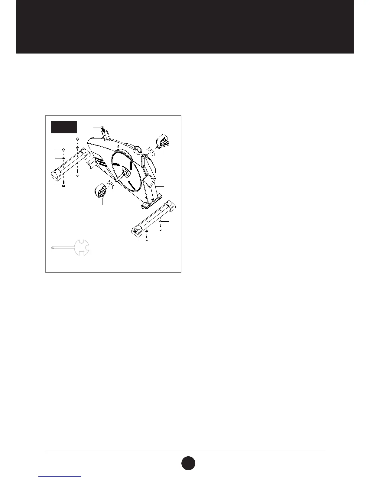
STEP 1
STEP 1: FRONT AND REAR STABILISERS
INSTALLATION
Attach the Front Stabiliser (6) onto the front curve
of the Main Frame (1) with 2 x Carriage Bolt (60),
2 x Flat Washer (58) and 2 x Cap Nut (59).
Tighten cap nuts with the Multi Hex Tool provided.
Attach the Rear Stabiliser (4) onto the front curve of
the Main Frame (1) with 2 x Hexagon Bolt (61),
2 x Flat Washer (58). Tighten cap nuts with the Allen
Wrench S6 provided.
The Cranks, Pedal Shafts, and Foot Pedals are marked
“R” for Right and “L” for Left.
Insert pedal shaft of Left Foot Pedal (27) into
threaded hole in the left crank. Turn the pedal shaft
by hand in counter-clockwise direction until snug.
Note: DO NOT turn the pedal shaft in the clockwise
direction, doing so will strip the threads.
Tighten the pedal shaft of Left Foot Pedal (27) with
the Multi Hex Tool with Phillips Screwdriver provided.
Insert pedal shaft of Right Foot Pedal (28) into
threaded hole in right crank. Turn the pedal shaft by
hand in clockwise direction until snug. Tighten the
pedal shaft of Right Foot Pedal (28) with the Multi
Hex Tool with Phillips Screwdriver provided.
TOOL:
Multi Hex Tool with Phillips Screwdriver
S13, S14, S15
59
58
60
6
58
61
4
28
27
70
1

 Loading...