ASSEMBLY STEPS
Recheck
all bolts and nuts are
tightened securely
before using the machine
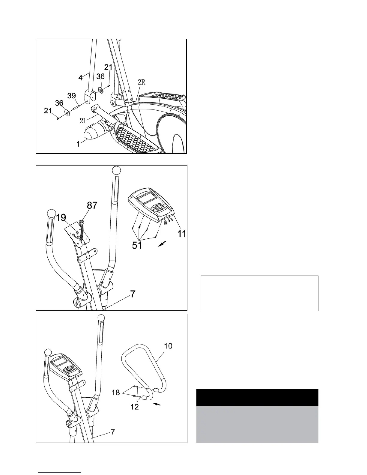
STEP 6
• ApplyasmallamountofgreasetoPedalTubeAxle(39).
A second person must hold the Left Pedal Tube (2L) inside
thebracketontheLeftLowerHandlebar(4).Insertthe
PedalTubeAxle(39)throughLowerHandlebar(4)and
the Pedal Tube (2L).
• PlaceanAxleCover(36)intoeachofthePedalTubes
(39). and insert and tighten Screw (21).
• RepeatthesameprocedureforRightLowerHandlebar
(4) and Right Pedal Tube (2R).
STEP 7
• InsertBatteriesintoConsol(seepage11).
• Removethe4pre-assembledScrews(51)fromthe
bottom of Monitor (11).
• ConnecttheplugofMiddleSectionSensorWire(87)to
theSensorSocketofMonitor(11).
• ConnecttheplugofHandPulseWire(19)tothe
Monitor (11).
• AttachtheMonitor(11)totheMonitorBracketofFront
Post (7) with 4 Screws (51).
STEP 8
• Removethe2pre-assembledScrews(18)and2Spring
Washer (12) from the Small Handlebar (10).
• SecuretheSmallHandlebar(10)tothewelded
handlebarbracketontheFrontPost(7)with2Screws
(18) and 2 Spring Washers (12) .
Caution: Ensure that cables are not damaged
during assembly or when tightening screws