27
77
79
79
9
2
8
77
79
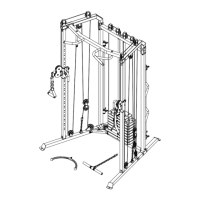
ASSEMBLY STEPS
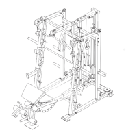
STEP 21:
1. Attach the Foot Plate (9) to the Centre Base (2)
and the Backrest Upright (8) with four M10 x
20 mm Button Bolts (77) and four M10
Locknuts (79).
See steps 3–8, 12, 14–16, and 18–20. Tighten
all of the Bolts, Screws, and Locknuts used
in these steps.
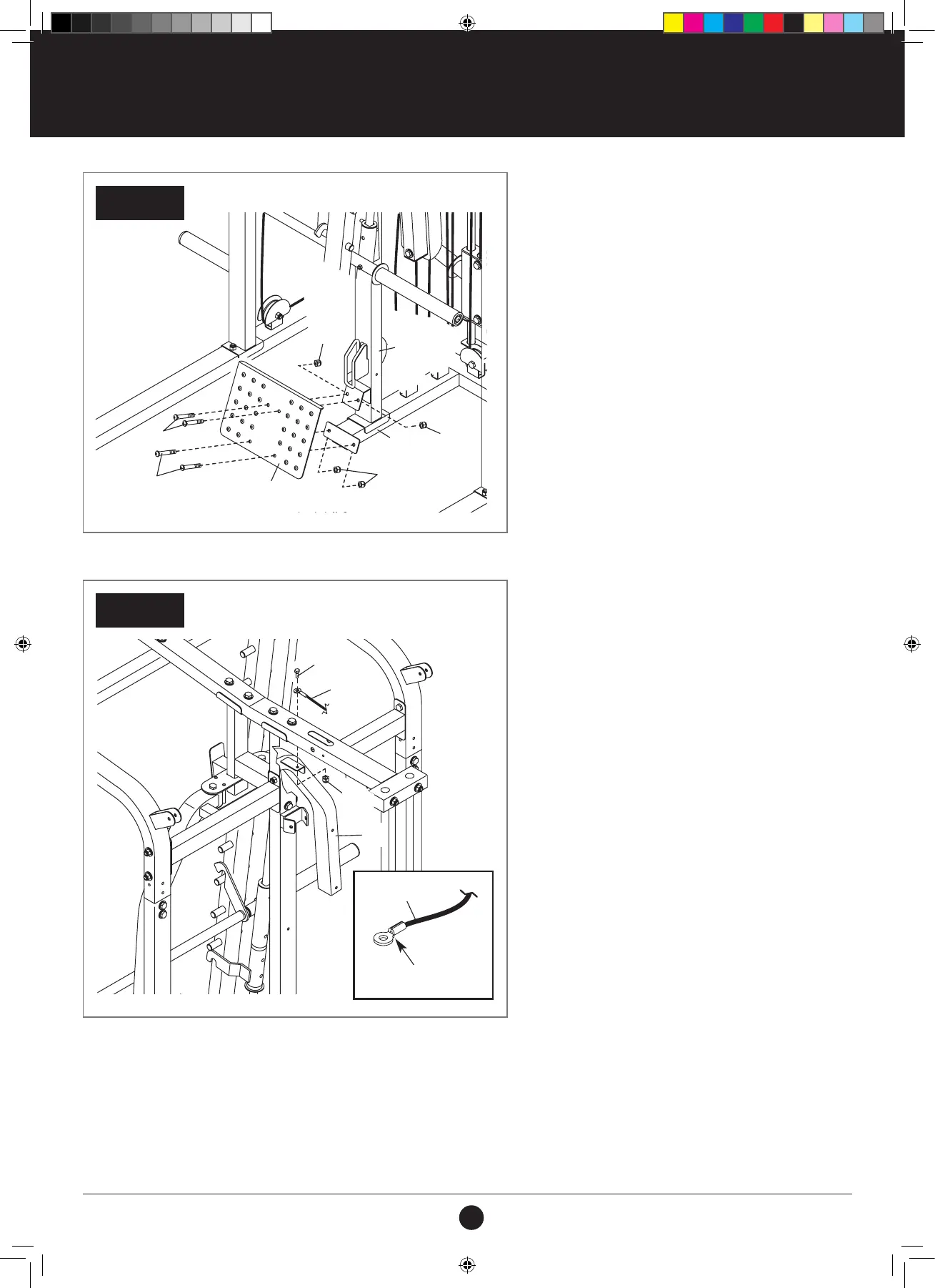
STEP 22:
1. See the CABLE DIAGRAMS on pages 53 and 54 to
identify the cables as you assemble them.
2. Identify the Buttery Cable (71).
3. See the inset drawing. Orient one end of the
Buttery Cable (71) so that the at side is facing
downward as shown.
4. Attach the end of the Buttery Cable (71) to
the Right Arm (11) with an M8 x 20 mm Shoulder
Bolt (85) and an M8 Locknut (78).
Do not overtighten the Locknut; the
Buttery Cable must pivot easily.
NOTE: STEPS 22–51 ARE SHOWN FROM
THE REAR OF THE WEIGHT RACK.
STEP 22
STEP 21
85
71
71
11
Flat Side
78
REAR OF THE WEIGHT RACK
Flat Side
71
71
79
79
79
79
9
2
8
77
77
11
85
#21M05T035 Multifunction Smith Machine UM A4.indd 27 2021/06/24 11:27 AM