28
88
61
60
84
79
8
39
39
71
88
84
71
61
39
79
39
60
8
96
46
71
40
58
79
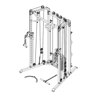
ASSEMBLY STEPS
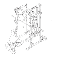
STEP 23:
1. Identify the V-pulleys (60), the 90mm Pulleys
(not shown), and the 115 mm Pulleys (not
shown).
2. Route the Buttery Cable (71) over a V-pulley
(60). Attach the V-pulley, a Short Metal Cable
Trap (61), an M10 Washer (84), and two Full
Guards (39) to the Backrest Upright (8) with an
M10 x 63 mm Bolt (88) and an M10 Locknut (79).
Make sure that the Short Metal Cable Trap is
oriented to hold the Buttery Cable in the
groove of the V-pulley.
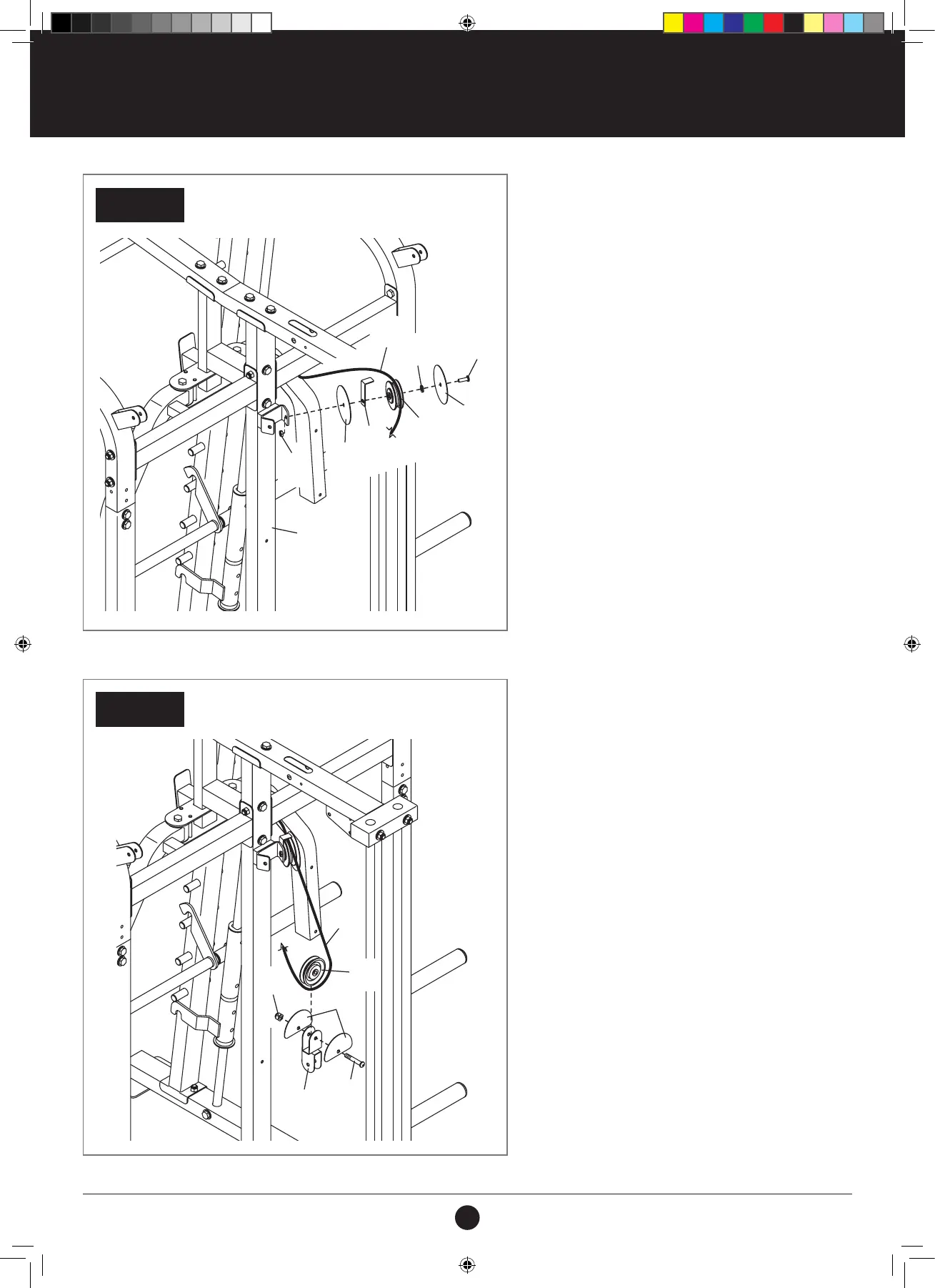
STEP 24:
1. Route the Buttery Cable (71) under a 90 mm
Pulley (58). Attach the 90 mm Pulley and two
Half Guards (40) to the Double U-bracket (46)
with an M10 x 45 mm Bolt (96) and an M10
Locknut (79).
STEP 24
STEP 23
REAR OF THE WEIGHT RACK
REAR OF THE WEIGHT RACK
71
58
79
46
96
40
#21M05T035 Multifunction Smith Machine UM A4.indd 28 2021/06/24 11:27 AM