29
39
39
60
71
79
61
84
8
88
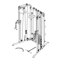
ASSEMBLY STEPS
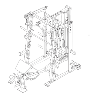
STEP 25:
1. Route the Buttery Cable (71) over a V-pulley
(60). Attach the V-pulley, a Short Metal Cable
Trap (61), an M10 Washer (84), and two Full
Guards (39) to the Backrest Upright (8) with an
M10 x 63 mm Bolt (88) and an M10 Locknut (79).
Make sure that the Short Metal Cable Trap is
oriented to hold the Buttery Cable in the
groove of the V-pulley.
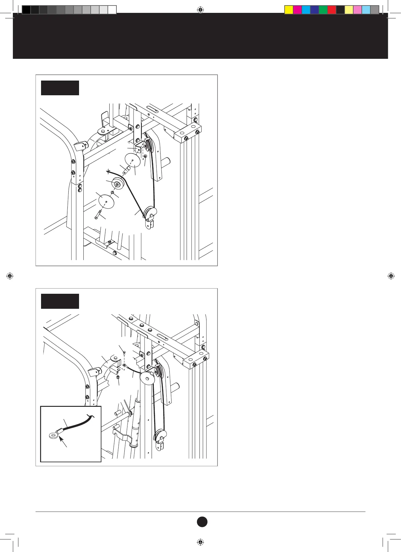
STEP 26:
1. See the inset drawing. Orient the other end of
the Buttery Cable (71) so that the at side is
facing downward as shown.
2. Attach the Buttery Cable (71) to the Left Arm
(10) with an M8 x 20 mm Shoulder Bolt (85)
and an M8 Locknut (78). Do not overtighten the
Locknut; the Buttery Cable must pivot easily.
STEP 26
STEP 25
REAR OF THE WEIGHT RACK
REAR OF THE WEIGHT RACK
85
78
71
10
71
Flat Side
Flat Side
71
10
85
88
8
84
71
39
39
79
61
60
78
71
#21M05T035 Multifunction Smith Machine UM A4.indd 29 2021/06/24 11:27 AM