36
72
47
86
100
72
47
86
100
79
84
75
84
32
Rods
3
54
137
75
58
52
53
100
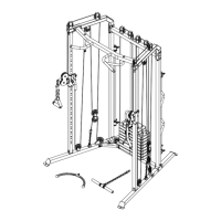
ASSEMBLY STEPS
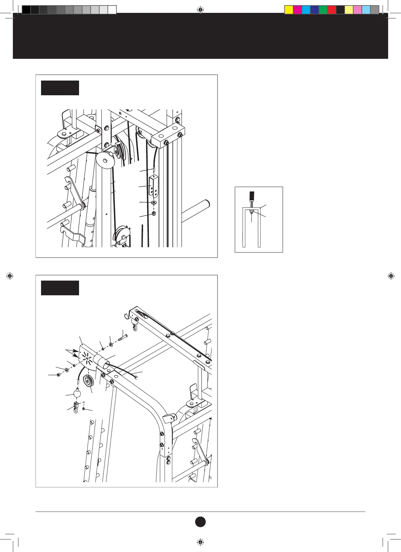
STEP 39:
1. Attach the Low Cable (72) to the U-bracket (47)
with an M6 Washer (86) and an M6 Locknut
(100).
See the inset drawing. Do not overtighten
the Locknut; it should be threaded onto
the end of the Low Cable so that only two
threads are showing below the Locknut.
STEP 40:
IDENTIFY THE LONG CABLE (54)
1. Attach a Cable Stop (52), a Clip (53), and an
M6 Locknut (100) to the Long Cable (54) as
described in step 27.
Make sure that at least two threads of the
Long Cable show past the Locknut.
2. Next, route the Long Cable (54) over a 90 mm
Pulley (58) and upward through a Swivel Arm
(32) and the Left Upright (3).
Make sure that the Long Cable is routed on
the indicated side of the small rods inside
the Swivel Arm.
3. Attach the 90 mm Pulley (58) inside the Swivel
Arm (32) with an M10 x 53 mm Bolt (137), two
M10 Washers (84), two 6 mm Spacers (75), and
an M10 Locknut (79).
STEP 40
STEP 39
REAR OF THE WEIGHT RACK
REAR OF THE WEIGHT RACK
72
100
47
100
47
72
137
100
54
84
32
75
75
53
58
3
52
Rods
79
84
#21M05T035 Multifunction Smith Machine UM A4.indd 36 2021/06/24 11:27 AM