44
82
135
109
79
84
105
107
Hexagonal
Holes
78
108
143
107
108
50
50
82
82
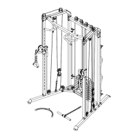
ASSEMBLY STEPS
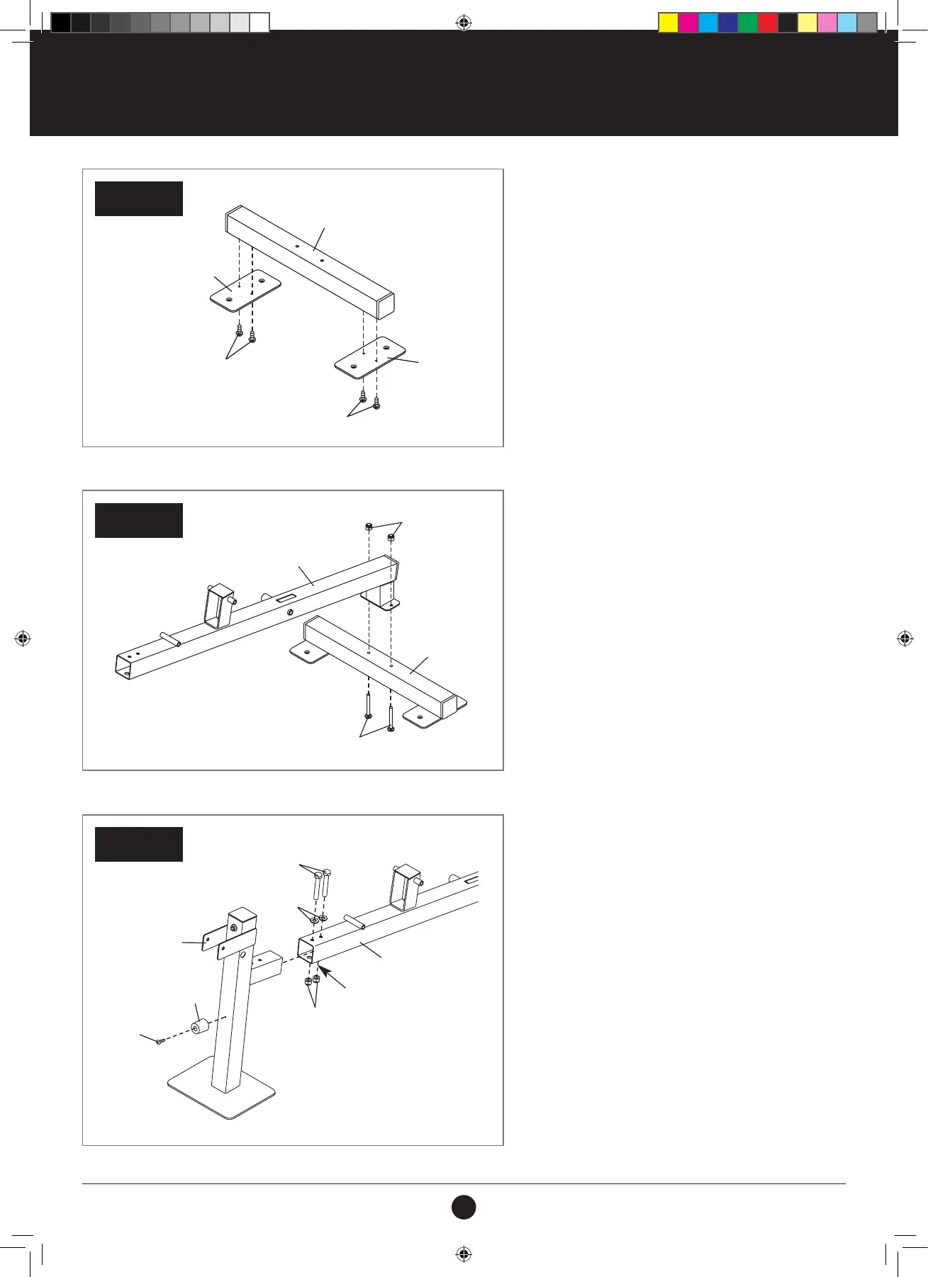
STEP 57:
1. Attach the Bench Stabiliser (108) to the Bench
Frame (107) with two M8 x 76 mm Carriage Bolts
(143) and two M8 Locknuts (78).
Do not tighten the Locknuts yet.
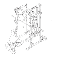
STEP 56:
1. Attach two Stabiliser Feet (50) to the
Bench Stabiliser (108) with four M4 x 19 mm
Self-tapping Screws (82).
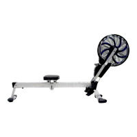
STEP 58:
1. Attach the Leg Bumper (135) to the Front Leg
(109) with an M4 x 19 mm Self-tapping Screw
(82).
2. Attach the Front Leg (109) to the Bench Frame
(107) with two M10 x 75 mm Bolts (105), two
M10 Washers (84), and two M10 Locknuts (79).
Make sure that the Locknuts are inside the
indicated hexagonal holes.
3. See step 57. Tighten the M8 Locknuts (78).
STEP 56
STEP 58
STEP 57
107
105
109
135
79
82
84
Hexagonal
Holes
108
107
108
78
50
50
82
82
143
#21M05T035 Multifunction Smith Machine UM A4.indd 44 2021/06/24 11:28 AM