45
117
146
118
146
146
86
86
110
106
Grease
79
109
79
106
109
110
Grease
130
118
94
Holes
94
130
78
78
111
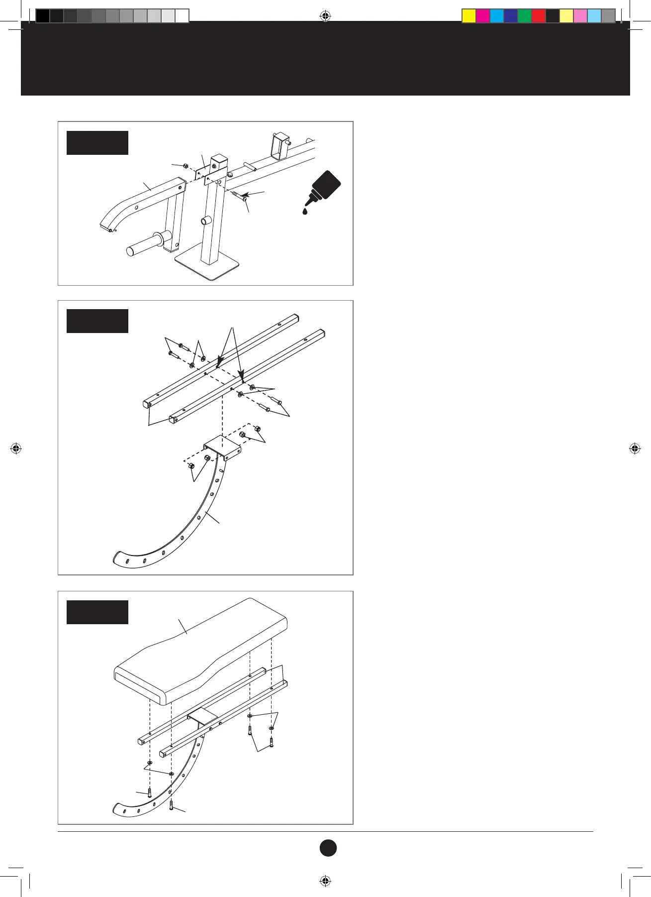
ASSEMBLY STEPS
STEP 59:
1. Apply grease to an M10 x 81 mm Bolt (106).
2. Attach the Leg Lever (110) to the Front Leg (109)
with the M10 x 81 mm Bolt (106) and an M10
Locknut (79).
Do not overtighten the Locknut; the Leg
Lever must pivot easily.
STEP 60:
1. Orient the two Backrest Frames (118) so that the
indicated holes are nearer the bottom.
2. Attach the Backrest Frames (118) to the Backrest
Bracket (111) with four M8 x 42 mm Bolts (130),
four M8 Washers (94), and four M8 Locknuts
(78).
Do not tighten the Locknuts yet.
STEP 60
STEP 59
111
118
130
130
94
94
78
78
Holes
STEP 61:
1. Attach the Backrest (117) to the Backrest Frames
(118) with four M6 x 45 mm Screws (146) and
four M6 Washers (86).
Do not tighten the Locknuts yet.
STEP 61
117
118
146
146
146
86
86
#21M05T035 Multifunction Smith Machine UM A4.indd 45 2021/06/24 11:28 AM