46
111
124
107
116
122
121
86
34
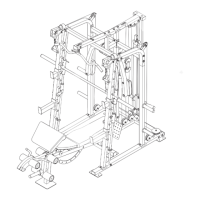
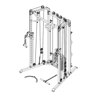
ASSEMBLY STEPS
STEP 62:
1. Attach the Seat (116) to the Seat Frame (122)
with two M6 x 40 mm Screws (121) and two M6
Washers (86).
2. Then, attach the other end of the Seat (116)
to the Seat Frame (122) with two M6 x 20 mm
Screws (34).
STEP 62
86
34
116
122
121
122
84
Grease
84
79
118
107
145
STEP 63:
1. Pull the Bench Knob (124) outward and insert
the Backrest Bracket (111) through the Bench
Frame (107).
2. Engage the Bench Knob into the Backrest
Bracket.
STEP 64:
1. Apply grease to an M10 x 180 mm Bolt (145).
2. Attach the Backrest Frames (118) and the Seat
Frame (122) to the Bench Frame (107) with the
M10 x 180 mm Bolt (145), two M10 Washers
(84), and an M10 Locknut (79).
Do not overtighten the Locknut; the
Backrest Frames and the Seat Frame (122)
must pivot easily.
STEP 64
STEP 63
Grease
111
107
107
122
79
84
84
118
145
124
#21M05T035 Multifunction Smith Machine UM A4.indd 46 2021/06/24 11:28 AM