Recheck
all bolts and nuts are
tightened securely
before using the machine
1567-6
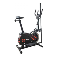
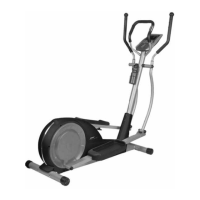
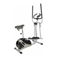
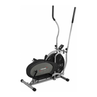
4. ASSEMBLY STEP
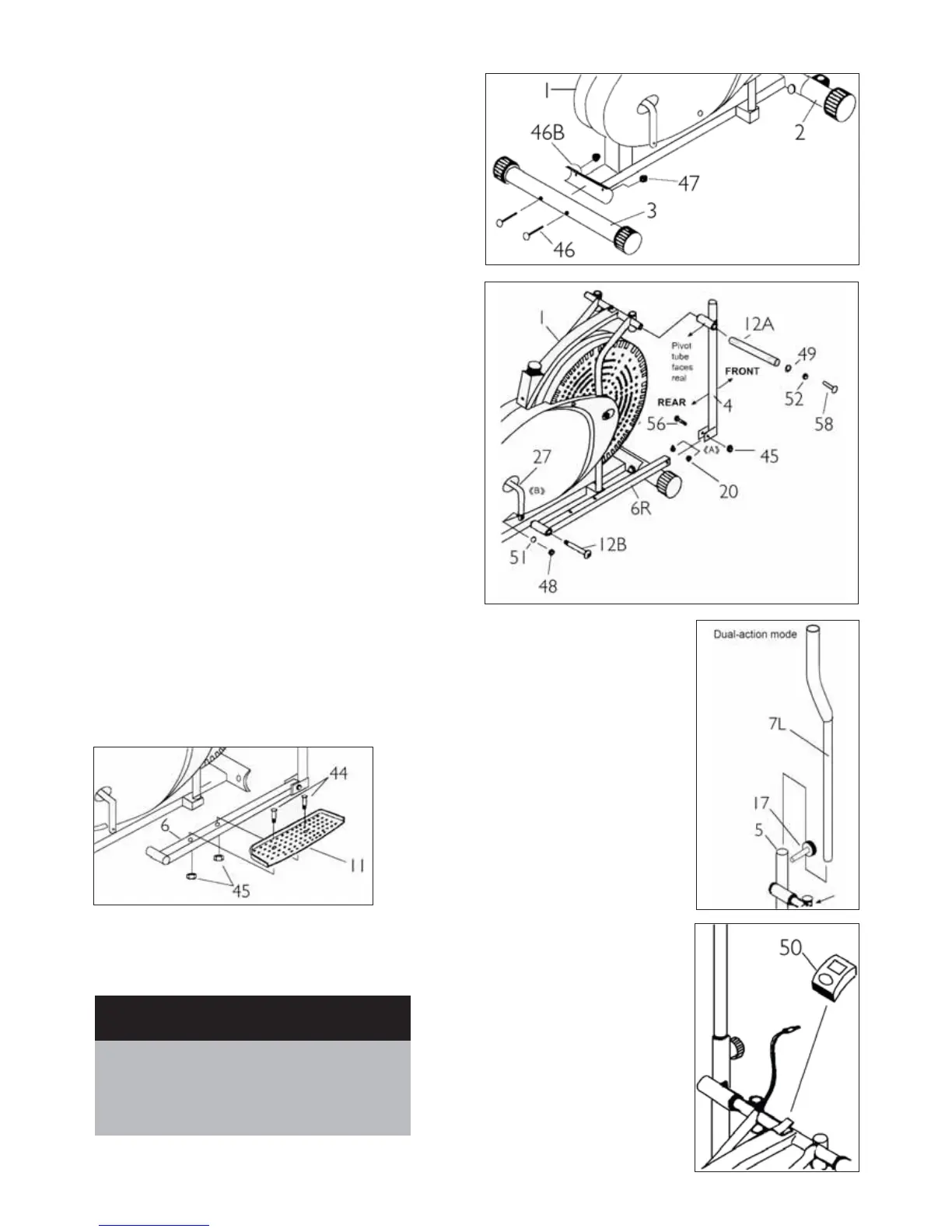
STEP 01
• Attach the Back Stabilizer (3) to Main Frame (1) with the
Carriage Bolt (46), Curve Washer (46B) and Nut Caps (47)
• Attach the Front Stabilizer (2) to Main Frame (1) with
the Carriage Bolts (46), Curve Washer (46B) and Nut Caps
(47)
STEP 02
• Attach the right Coupler Bar (4) to the right Pedal Tube
(6R) with Bolts (56), Steel Bushings (20) and Nylon Nuts
(45)
• Attach the Handle Bar Shaft (12A) through the hole
on right Couple Bar (4) to the Main Frame (1) with
D Shape Washer (49), Spring Washer (52) and Hinge
Screw (58)
• Attach the right Pedal Tube (6R) to the Crank (27) with
Spring Washer (51), Nylon Nut (48) and Pedal Hinge
Bolt 1/2” (12B)
• Repeat the above steps for the left side.
STEP 04
• Insert the left handlebar
(7L) into the hole on left
coupler bar (5) on desired
height tightly with locking
knob (17).
• Repeat the above steps for
the right side.
STEP 03
• Attach the Pedal (11) to the Pedal Tube (6) with two
3/8”x50mm Bolts (44) and two 3/8 “ Nylon Nuts (45)
• Repeat the above step for the left pedal assembly
STEP 05
• Connect the sensor wire to
the Computer (50)
• Attach the Computer (50)
to the Main Frame (1)