Do you have a question about the TRONXY VEHO 600-2E and is the answer not in the manual?
Guidelines for usage environment, safety, emergency procedures, and warranty disclaimers.
Recommended room conditions and location of additional software files.
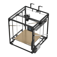
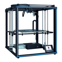
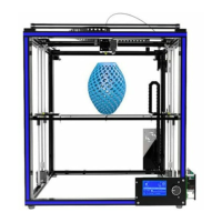
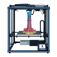
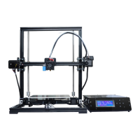
Details on printing principles, size, speed, slicing software, and connection methods.
Recommended temperature/humidity, voltage, output, dimensions, and weight.
Lists various aluminum profiles and rails for the printer frame.
Includes guide rails, assemblies, beams, and crossbars.
Motors, sliders, brackets, gears, and drag chains.
Ribbon cables, adapter boxes, and connectors.
Synchronous gears, hot bed, springs, leveling nuts, power supply, main control box.
Limit switches, card reader, TF card, and filament.
Wrenches, screwdrivers, and shovels provided for assembly.
Various screws and boat nuts for securing components.
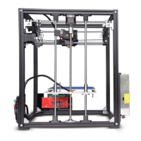
Step-by-step guide for assembling the printer's main frame structure.
Lists required parts like triangles, foot pads, and screws for frame assembly.
Instructions on using triangular connectors to build the frame.
Guidance on attaching the foot pads to the assembled frame base.
Explanation of how boat nuts are used to secure frame components.
Detailed steps for installing the foot pads onto the frame.
Steps for attaching the vertical 3030R profiles to the base.
Connecting the top horizontal profiles to form the upper frame.
Attaching end caps to the frame corners for a finished look.
Installing the Z-axis motors onto the frame using screws.
Attaching the Y-axis guide rails and sliders to the frame.
Instructions for correctly combining guide rails with slider components.
Attaching the front and rear seat aluminum blocks for the Y-axis.
Securing the Y-axis guide rails to the frame structure.
Mounting the Z-axis guide rails onto the frame using screws.
Tightening screws to fix the Z-axis guide rails in place.
Instructions to install the remaining three Z-axis guide rails.
Steps to assemble and install the Z-axis screw rod components.
Instructions to loosen specific jack screws for assembly.
Visual guide for connecting the screw rod with the bearing and base plate.
Step-by-step visual guide for fitting the screw rod assembly.
Attaching the print head assembly to the X-axis slider.
Connecting extruder and filament detector wires to the print head.
Attaching the X-axis guide rail and slider to the frame.
Mounting the bracket for the X-axis drag chain.
Instructions to move the X-axis sliders to their furthest back position.
Securing the X-axis guide rail onto the slider component.
Connecting extruder and filament detector wires to the print head.
Finalizing the print head attachment with screws.
Mounting supporting and fixing components for the X-axis drag chain.
Attaching the 30-pin ribbon cable adapter box.
Attaching the X-axis drag chain to the printer frame.
Connecting the flat cable into the drag chain assembly.
Inserting the ribbon cable into the adapter box socket.
Mounting the adapter box and connecting the X-axis motor line.
Mounting the brackets for the Y-axis drag chain.
Securing the Y-axis drag chain to the brackets.
Final steps to attach the Y-axis drag chain.
Assembling and attaching the Y-axis motor and related components.
Attaching synchronous gears and the 2GT-160 belt.
Securing the Y-axis motor assembly to the frame.
Mounting the three synchronous gears onto their respective shafts.
Instructions for properly tensioning the drive belt.
Gathering beams, fixing strips, leveling nuts, and springs for hot bed.
Steps to assemble the hot bed mounting structure.
Securing the assembled hot bed structure to the printer frame.
Placing and securing the hot bed platform onto the frame.
Attaching brackets for the filament rack.
Mounting the power supply unit and main control box.
Attaching the Y-axis limit switch to the frame.
Extracting Y-stop and Y motor wires from the main control box.
Finalizing the installation of the control box by tightening screws.
Connecting the Y-STOP line to its designated connector.
Attaching the reinforced crossbars for structural support.
Mounting the filament rack onto the printer frame.
Securing the fixing rods to the frame.
Attaching brackets for the filament rack.
Steps for installing the drive belts onto the pulleys.
Instructions for tensioning the drive belts correctly.
Steps for installing the drive belts onto the pulleys.
Final steps for ensuring proper belt tension.
Steps for installing the drive belts onto the pulleys.
Final steps for ensuring proper belt tension.
Method for adjusting the tension of the X-axis belts.
Method for adjusting the tension of the Y-axis belts.
Diagram showing the location of all connecting lines and sockets.
Steps for connecting wires to the main control box.
Visual guide to identify different wire types for connection.
Steps for installing the 30-pin ribbon cable into the drag chain.
Connecting the Z-STOP lines to the photoelectric switches.
Mounting the Z-axis photoelectric switches at the lowest position.
Navigating the menu to start the automatic leveling process.
Choosing the automatic leveling option from the tool menu.
The system automatically performs leveling detection.
Performing Z offset operation after successful leveling.
Adjusting the Z offset for optimal nozzle-to-bed distance.
Placing paper and adjusting nozzle to achieve slight resistance.
Finalizing the Z offset adjustment by confirming on screen.
Using leveling nuts to adjust the platform based on auto-leveling failure readings.
Rotating nuts counterclockwise for high values and clockwise for low values.
Performing automatic leveling again after manual nut adjustments.
Navigating to the manual leveling option via the tool menu.
Recommends setting Z offset before starting manual leveling.
Adjusting nuts at points A, B, C, D to set nozzle-bed distance.
Employing a leveling card to feel resistance for accurate adjustment.
Steps to access the language selection menu via System > Language.
Choosing the preferred language from the available options.
Critical note on ensuring E1 feed and E2 return to prevent blocking.
Guidance on identifying E1 and E2 filaments and their run-out detectors.
Warning about withdrawing existing filament before feeding new filament to avoid blockages.
Step-by-step guide for inserting both E1 and E2 filaments into the print head.
Steps to preheat the nozzle to 200°C for filament loading.
Icons and actions for retracting (E1-/E2-) and feeding (E1+/E2+) filaments.
Extruding E1 filament until it flows from the nozzle.
Steps to retract E1 filament using the stop icon.
Extruding E2 filament until it flows from the nozzle.
Steps to retract E2 filament using the stop icon.
Guidelines for inserting TF card, handling read errors, and formatting.
Choosing a file from the TF card and initiating the printing process.
Adjusting Z compensation when the nozzle is too close to the print bed.
Adjusting Z compensation when the nozzle is too far from the print bed.
Achieving good extrusion and adhesion with correct nozzle height.
Steps to download and install the Cura slicing software.
How to change the display language within the Cura software.
Steps to add a new printer manually in Cura.
Setting up the printer profile as a custom FFF printer.
Configuring print size, number of extruders, and heated bed settings.
Setting nozzle size and filament diameter for Extruder 1.
Setting nozzle size and filament diameter for Extruder 2.
Importing a pre-made profile file for the printer.
Verifying successful import of the printer configuration file.
Switching to the pre-configured VEHO-600 printing profile.
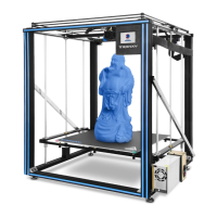
Importing a model file for slicing, with an example of a two-color model.
Assigning specific model parts to Extruder 2 for printing.
Combining multiple selected model parts into a single print job.
Performing the slicing operation and exporting the file to the TF card.
Checks for power, voltage, screen, wiring, and fuse issues.
Solutions for TF card reading problems, including formatting and replacement.
Diagnosing issues with filament extrusion, temperature, knots, and insertion.
Addressing issues like bed leveling, dirt, nozzle distance, temperature, and print speed.
Tips for removing models and troubleshooting heating failures.
Causes for motor step loss, noise, and vibration.
Addressing model shifting and filament feed problems.
Troubleshooting no screen, blue screen, touch malfunction, and garbled display.
Addressing wiring, automatic restart, heat dissipation, and motherboard damage.
Solutions for driver installation, serial port selection, and parameter mismatch.
| Build Volume | 600 x 600 x 600 mm |
|---|---|
| Print Technology | FDM |
| Layer Resolution | 0.1 - 0.4 mm |
| Nozzle Diameter | 0.4 mm |
| Filament Diameter | 1.75 mm |
| Max Print Speed | 150mm/s |
| Connectivity | USB, SD card |
| Frame Material | Aluminum |
| Number of Extruders | 2 |
| Heated Bed | Yes |
| Nozzle Temperature | Up to 260°C |
| Display | Touchscreen |
| Supported Materials | PLA, ABS, PETG, TPU |
| Power Supply | 110V/220V |
| Bed Temperature | Up to 100°C |