Do you have a question about the TRONXY X5 and is the answer not in the manual?
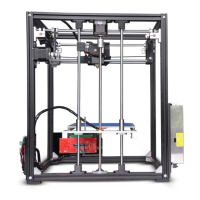
Assemble Y-axis motor, holder, and pulley with M3-45mm screws and M4 T-Nuts.
Mount Z axis motor, holder, lead screw, and coupling with M3-45mm screws and M4 T-Nuts.
Attach X-axis sliding rods and the extruder assembly.
| Build Volume | 330 x 330 x 400 mm |
|---|---|
| Layer Resolution | 0.1 - 0.4 mm |
| Nozzle Diameter | 0.4 mm |
| Filament Diameter | 1.75 mm |
| Print Speed | 30 - 100 mm/s |
| Connectivity | USB, SD Card |
| Supported Materials | PLA, ABS, PETG, TPU |
| Frame Material | Aluminum |
| Display | LCD Touchscreen |
| Printing Technology | FDM (Fused Deposition Modeling) |
| Extruder Type | Single |
| Bed Temperature | Up to 100°C |
| Nozzle Temperature | up to 260 °C |
| Software | Cura, Repetier-Host |
| Print Bed | Heated |
| Power Supply | 24V |