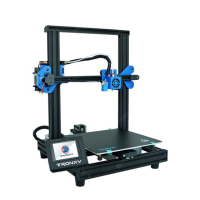
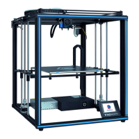
This document provides a comprehensive guide for the TRONXY VEHO600 3D Printer, covering its function, technical specifications, usage, and maintenance.
Function Description
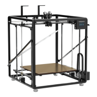
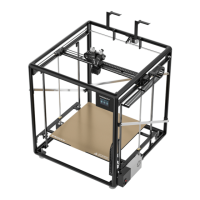
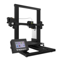
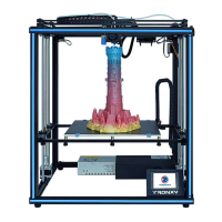
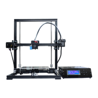
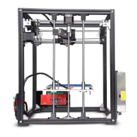
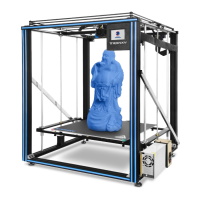
The TRONXY VEHO600 is a Fused Deposition Molding (FDM) 3D printer designed for creating three-dimensional objects from digital designs. It operates by extruding a molten thermoplastic material layer by layer to build the desired shape. The printer is equipped with features for automatic leveling, filament detection, and a user-friendly interface for control and monitoring.
Important Technical Specifications
- Printing Principle: FDM (Fused Deposition Molding)
- Print Size: 600 x 600 x 600 mm
- Print Thickness: 0.1-0.4 mm (Optional)
- Positioning Accuracy (X/Y/Z): X/Y: S0.01875 mm, Z: S0.00375 mm
- Number of Printheads: 1
- Nozzle Diameter: 0.6 mm (standard), 0.8 mm
- Print Speed: 20-150 mm/s (60 mm/s recommended)
- Moving Speed: Monochrome
- Compatible Filaments: PLA, ABS, PETG, WOOD, TPU
- Slicing Software: Cura
- Input Format: STL, OBJ, DAE, AMF, G-CODE
- Output Format: G-Code
- Connection Method: TF card, USB disk, USB cable (for skilled users)
- Input Voltage: 110-230V, 50-60HZ
- Power Output: 24V/360W
- Machine Size: 900 x 872 x 1100 mm
- Machine Weight: ≈38 kg
- Hot Bed Temperature: 100°C (Max)
- Nozzle Temperature: 275°C (Max)
- Ambient Operating Temperature: 8°C - 40°C
- Ambient Operating Humidity: 20% - 80%
The printer's structure includes a filament rack, Y-axis synchronizing lever, filament breaking detector, X-axis left and right sliders, extruder, print head, main control box, printing platform, Z-axis limit metal sheet, Z1 and Z2 photoelectric switches, X-axis guide rail, cable socket, Y-axis motor, automatic leveling detector, Z-axis guide rail, screw rod, reinforced crossbar, leveling nut, Z1 and Z2 motors, foot mat, X-axis motor, and various ports (TF, USB type B, USB stick socket).
Usage Features
- Unpacking and Inspection: Upon unpacking, users are instructed to verify the packing list to ensure all parts are present and undamaged. Any missing or damaged parts should be reported to after-sales service immediately.
- Environment: The printer should be operated in a well-ventilated, dry, clean, and flat environment.
- Safety Precautions: Due to high-speed moving parts, children should not operate the printer unsupervised. Unattended operation is not recommended. In emergencies, the power can be turned off directly.
- Temperature and Humidity: Optimal room temperature for printing is 8°C-40°C, with humidity between 20%-80%. Operating outside this range may result in poor print quality.
- TF Card: The provided TF card contains video tutorials, software, and other relevant information.
- Frame Assembly: The manual details the step-by-step assembly of the machine frame, including the installation of triangle components, foot pads, and various profiles.
- Motor and Guide Rail Installation: Instructions are provided for installing the Z-axis motors, left and right Y-axis guide rails, and Z-axis guide rails, emphasizing correct orientation and tightening of screws.
- Screw Rod Assembly: The process of installing the screw rod assembly, including loosening and tightening jack screws on the Z motor coupling and bearing seat, is outlined.
- X-axis Guide and Print Head Installation: Detailed steps for attaching the X-axis guide rail, drag chain brackets, and print head are provided, with specific screw types and quantities.
- Drag Chain and Ribbon Cable Installation: Instructions for installing the X-axis and Y-axis drag chains, ribbon cables, and adapter boxes, including how to pry open covers, insert cables, and connect motor lines.
- Belt Installation and Adjustment: The manual guides users through installing the X-axis and Y-axis belts, highlighting the importance of maintaining a 0.5-1mm gap and tightening the belts properly. Adjustment methods for both X-axis and Y-axis belts are clearly explained.
- Hot Bed Installation: Steps for installing the hot bed, support plate fixing strips, and beams are provided, with an emphasis on placing the hot bed bottom-up for easier assembly of other parts.
- Electrical Connections: A detailed diagram illustrates the location of all connecting lines and sockets, including Y-axis motor, 30 Pin Ribbon Cable, Z1 and Z2 photoelectric switches, Z1 and Z2 motor lines, hot bed line, power line, BTEMP line, and AC hot bed line. Users are instructed to loosen the main control box cable, insert the ribbon cable into the adapter box, and connect the X motor line.
- Z-axis Photoelectric Switch Installation: Instructions for installing the Z1 and Z2 photoelectric switches at the lowest position (above the power fixture) and adjusting them later. The manual explains how to move the Z2 photoelectric switch up until the red light turns off, indicating the correct position.
- Print Platform Leveling (Automatic):
- Access the automatic leveling detection interface via "System" -> "Tool" -> "Level" -> "Auto".
- The system automatically performs leveling detection. If successful, proceed to Z offset. If leveling fails (error too large), adjust the leveling nuts under the platform based on the displayed values and re-detect.
- After successful leveling, enter the "Z offset" interface. The print head moves to the middle of the hot bed. Manually lower the print head to approximately 0.1mm from the hot bed (using an A4 paper as a guide).
- Print Platform Leveling (Manual):
- Before manual leveling, set the Z offset (refer to automatic leveling instructions).
- Access the manual leveling interface via "System" -> "Tool" -> "Level" -> "Manual".
- Click the four points (A, B, C, D) in sequence. The print head moves to each corresponding position. Adjust the leveling screw under the platform at each point until the nozzle is approximately 0.1mm from the platform (using an A4 paper).
- The manual explains how to adjust the leveling nut: counterclockwise to lower the heatbed, clockwise to raise it.
- Filament Loading and Unloading:
- Insert the filament by pressing the extruder's elastic buckle and pushing the filament in.
- Control the extruder via "Tool" -> "Filament". Click "Start Heating" and wait for the temperature to reach 200°C. Use (E1-) to retract filament and (E1+) to feed filament.
- Print Test:
- Insert the TF card (metal face up) into the desktop card slot. Ensure the card is FAT32 formatted and print data is in the root directory with numerical file names.
- On the printer, select "Print" from the main menu. Choose a file and click the play icon to start printing.
- Real-time Adjustment During Printing: The manual explains how to adjust hot bed temperature, printing speed, and nozzle temperature in real-time using the "Adjust" menu.
- Troubleshooting Extrusion Issues:
- If the hot bed and nozzle are too close, adjust Z compensation (arrow 1).
- If the hot bed and nozzle are too far apart, adjust Z compensation (arrow 2).
- Proper nozzle height ensures good extrusion and adhesion.
- Slice Software Installation:
- Install "Ultimaker_Cura-amd64" on the computer.
- Add a printer: select "Add a non-networked printer", choose "Tronxy XY-2", and enter "VEHO-600" as the printer name.
- Configure machine settings: set X, Y, Z dimensions to 600 mm each.
- Import configuration file: go to "Preferences" -> "Configure Cura..." -> "Profiles" -> "Import" and select "Veho - 600 configuration file.curaprofile" from the TF card.
- Change nozzle setting: in Cura, change the nozzle size to 0.6mm.
- Model Slicing:
- Switch to the "VEHO-600" preset profile.
- Import a 3D model.
- Click "Slice" and export the G-code file to the TF card for printing.
Maintenance Features
- Unauthorized Modification: Unauthorized modification or disassembly that damages core components voids the warranty.
- Troubleshooting Guide: The manual includes a comprehensive "Failure Cause Analysis" section to help users diagnose and resolve common issues:
- Machine Cannot Start: Check power connections, supply voltage, screen/power supply damage, wire damage, and power fuse.
- TF Card Read Errors: Check card reader, format TF card if unreadable, ensure correct insertion, rename files with illegal characters, and replace damaged TF cards.
- Filament Extrusion Issues: Check print head temperature (must be >200°C for PLA), check for knotted filaments, and ensure filaments/pipes are correctly inserted.
- Excessive Filament Softness/Hardness: If the print head temperature is too high, filaments become too soft. If the temperature is too low, they become too hard.
- Inconsistent Filament Diameter: Ensure filament diameter matches the setting in slicing software to prevent insufficient extrusion.
- Blocked Filaments/Nozzle: Check for dirt blocking filaments or nozzle during extrusion.
- Poor Quality Filaments: Replace with better quality filaments if issues persist.
- First Layer Warping: Check hot bed leveling, hot bed surface cleanliness, nozzle-to-platform distance (should not be too high), hot bed temperature, and print speed (not too fast).
- Model Adhesion Issues: Heat the hot bed to 50-70°C for easier removal with a shovel. TRONXY magnetic stickers are recommended for better adhesion.
- Heating Failure: Check heating rod and thermistor for poor contact or damage, verify target temperature in slicing software, and check if the thermistor wire has fallen off.
- Motor Out of Step: Check belt tightness, pulley lock, current voltage, X/Y/Z axis motion smoothness, print speed (not too fast), environment temperature (not too high), and consider flashing firmware.
- Abnormal Motor Noise/Vibration: Check motor line connections (bad contact, loose, wrong), motor temperature (not too high), motor damage, and printing load (not too heavy). Consider flashing firmware.
- Model Dislocation/Fault: Clean or replace nozzle if feeding is not smooth, check print speed (not too fast), and replace poor quality filaments.
- Filament Feeding Motor Noise/Vibration: Check for blocked nozzle and smooth filament feeding.
- Screen Related Issues: Restart or check cable connection for no screen/blue screen. Check for overly tight screws if the touch screen malfunctions. Restart for garbled/splash screen, static, or ground connection issues.
- Motherboard Related Issues: Check wiring installation for no response. Automatic shutdown/restart may indicate abnormal firmware or damaged "resume print after power failure" module. Lower ambient temperature for insufficient heat dissipation. No response may indicate motherboard damage.
- Unable to Connect to Printer: Check driver installation, serial port selection, and software parameter matching.