EasyManua.ls Logo

TRONXY X5S - User Manual

TRONXY X5S
16 pages
Print Icon
To Next Page IconTo Next Page
Loading...
Step 1. Assemble base frame
Assemble parts specifications and quantity
Aluminium profile 1 20*20*530mm
4pcs
Aluminium profile 2 20*20*460mm
2pcs
Aluminium profile 3 20*40*530mm
4pcs
Pad 4pcs
Screw PM5*25
12pcs
screw PM4*9
4pcs
Spacer M4
4pcs
T nut M4 4pcs
1.Lock the aluminium profile 1 2pcs, Aluminium profile 2 2pcs, aluminium 3 4pcs
together by 8pcs screw PM5*25, same as the illustration.
3.Lock the aluminium profile 1 2pcs with 4pcs screw PM5*25
Note: Do not tighten too much, enable they can be adjusted in further step.
Note: Before locking the screws, make sure the aluminum profile are aligned and vertical
Aluminium profile 1
Aluminium profile 1
Aluminium profile 2
Aluminium profile 3
2.Assemble the pad, spacer, screw PM4*9, T nut M4 with the aluminium profile 1
together,distance from the end around 20mm, same as the illustration
Aluminium profile 1
Question and Answer IconNeed help?

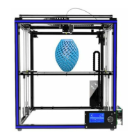
Do you have a question about the TRONXY X5S and is the answer not in the manual?

Summary

Step 1: Assemble Base Frame

Base Frame Assembly

Assemble the base frame using aluminium profiles, pads, spacers, and screws.

Step 2: Assemble Slider Plate

Slider Plate Attachment

Attach slider plates to the main frame using screws and T nuts.

Step 3: Assemble Printing Head

Printing Head Assembly

Assemble the printing head with the towline and holder, connecting it to the slider plates.

Step 4: Assemble XY Axis Motor and Wheel

XY Axis Motor and Pulley Setup

Mount XY axis motors, base plates, and pulley components to the frame.

Step 5: Assemble Belt

Drive Belt Installation

Install and tension the drive belts for the XY axes, ensuring proper gear engagement.

Step 6: Assemble Bearings and Z-Axis Motor

Z-Axis Motor and Bearing Assembly

Assemble Z-axis bearings, motor components, and fixed plates for vertical movement.

Step 7: Assemble Z Axis Component

Z-Axis Rod and Carriage Integration

Integrate sliding rods and lead screws into the Z-axis carriage for smooth vertical motion.

Step 8: Assemble Feeding Motor

Feeding Motor Mounting

Mount the feeding motor component onto the main framework.

Step 9: Assemble Printer Plateform

Printer Platform and Heatbed Setup

Assemble the printer platform, attach the heatbed, and connect it to the frame.

Step 10: Assemble Electronic Board

Electronic Board and Fan Cover Installation

Mount the electronic board, fan cover, and plastic pillars onto the frame.

Step 11: Assemble LCD

LCD Display and Holder Assembly

Assemble the LCD holder, display board, and knob, then fix it to the frame.

Step 12: Assemble Power Supply

Power Supply Unit Mounting

Mount the power supply unit securely onto the aluminium profile.

Step 13: Assemble Feeding Holder

Filament Feeding Holder Assembly

Assemble and mount the feeding holder plate for the filament spool.

Step 14: Assemble Decorative Strip and Feeding Tube

Feeding Tube and Decorative Strip Installation

Install the feeding tube and decorative aluminium profile seals.

Step 15: Assemble Limit Switch

Limit Switch Mounting

Mount the limit switches onto the frame and adjust their positions.

Step 16: Connecting Wire

Wiring and Cable Connections

Connect electronic components, motors, sensors, and power supply using specified cables.
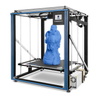
TRONXY X5S Specifications

General IconGeneral
BrandTRONXY
ModelX5S
Category3D Printers
LanguageEnglish

Related product manuals