6 EN
oil heater IDE 20 / IDE 30 / IDE 50 / IDE 60 / IDE 80
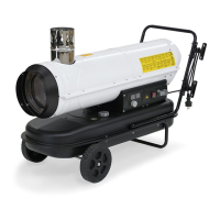
Device depiction
IDE 20
The side view of the operating elements shows the device
IDE20 by way of example.
IDE30/ IDE50/ IDE60/ IDE80
In addition, the devicesIDE30, IDE50, IDE60 and IDE80 come
with a fuel filter located at the side. The fuel tank cap(10) and
the tank filling level indication(11) of the devicesIDE50, IDE60
and IDE80 are located at the rear.
No. Designation
1 Combustion chamber housing
2 Flue pipe connection
3 Transport handle
4 Air inlet with protective grid
5 Fan and motor
6 Tank
7 Frame
8 Control panel
9 Wheel
10 Fuel tank cap
11 Tank filling level indication
12 Air outlet for hot air
13 External fuel filter (except for IDE20)
14 Danfoss injection pump (for IDE20: fuel pump)
 Loading...