EN 7
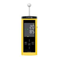
moisture measuring device T660
Setting the alarm limit value
Here you can determine the limit value for the alarm function.
Upon exceeding this value, the device emits an acoustic signal
and the indication ALARM flashes in the configuration
mode(17). The alarm function draws on the current measured
value.
The limit value can be determined within a range of 0 to 200.
1. Select ALARM whilst in configuration mode(17).
2. Press the OK button(10) to confirm.
ð The upper measurement value display(14) flashes.
3. Press the Up(7) or Down(9) button to activate or
deactivate the alarm.
ð On or Off will be indicated in the upper measurement
value display(14).
4. Press the Right/back button (8).
ð Depending on the selection, the alarm is either activated
or deactivated.
ð The lower measurement value display(16) flashes.
5. Press the buttons Right/back(8) or Left/menu(11) to select
a digit.
ð The selected digit flashes.
6. Press the Up(7) or Down(9) button to change the value of
the selected digit.
7. Repeat the steps 5. and 6. until the value is set as desired.
8. Press the OK button(10) for approx. 2 seconds.
ð The alarm was set based on your choice.
ð The device switches to measuring mode.
ð With activated alarm function the indicationALARM
continues to be displayed in the configuration
mode(17).
Adjusting the display illumination
The display illumination can be adjusted within a range of20
to100%. Another available setting is AL.on (always on). AL.on
features a brightness of 100 % and deactivates the automatic
switch-off function.
1. Select the lamp(18) whilst in configuration mode.
2. Press the OK button(10) to confirm.
3. Select the desired value by use of the Up(7) or Down(9)
button.
4. Press the OK button(10) for approx. 2 seconds.
ð The set value will be adopted.
ð The device switches to measuring mode.
Material settings
Here you can select the construction material for the
measurement. The following options are available:
• 0 no: No material selected.
• 1 An: The selected material is anhydrite screed.
• 2 CE: The selected material is cementitious screed.
Please note that in case of the settings1 and 2 an additional
value will be indicated in the upper measurement value
display(14).
It is a combination of the material(1or2) and the calculated
percentage.
Example: 2_7.5 (7.5 % with cementitious screed).
1. Select MAT whilst in configuration mode(17).
2. Press the OK button(10).
3. Select the desired value by use of the Up(7) or Down(9)
button.
4. Press the OK button(10) for approx. 2 seconds.
ð The device switches to measuring mode.
ð With either setting 1 or 2 the indication MAT continues
to be displayed in configuration mode(17).
Setting the offset
By use of CAL a single-point calibration can be carried out for
the selected sensor indications. All sensors are already factory-
calibrated and have a corresponding characteristic calibration
curve. By stating a calibration value (offset) a global shift of the
calibration curve, which has an effect on the entire measuring
range, is performed for the single-point calibration! The offset
value to be entered is that value by which the calibration curve
will be shifted.
Example:
The displayed value is always "5" too high => change the offset
value for this measurement channel to "-5".
The offset value's default setting is 0.0.
Note
Please note that changing the offset value brings about
an automatic reset of the measured values.
1. Select CAL whilst in configuration mode(17).
2. Press the OK button(10).
3. Use the buttons Left or Right to select a digit.
ð The selected digit flashes.
4. Press the Up(7) or Down(9) button to change the value of
the selected digit.
5. Repeat the steps 3. and 4. until the value is set as desired.
6. Press the OK button(10) for approx. 2 seconds.
ð The offset is set.
ð The device switches to measuring mode.
ð With set offset value the indication CAL continues to be
displayed whilst in configuration mode(17).
 Loading...