MOWERMAINTENANCE
NOTE: The maintenance proce-
dures in this section can be applied
to all models unless otherwise
noted.
WARNING
Before performingany maintenanceprocedures,stop the engine, wait
for all movingparts to stop, and allow the engine to cool. Disconnect
the sparkplug wire and move it away from the sparkplug. Removethe
ignitionkey on electricstart models.
Failureto do thiswill resultin personalinjuryor propertydamage.
WHEELSPEEDADJUSTMENT
(SingleSpeedModels:34021, 34021C, 34321 and34321C)
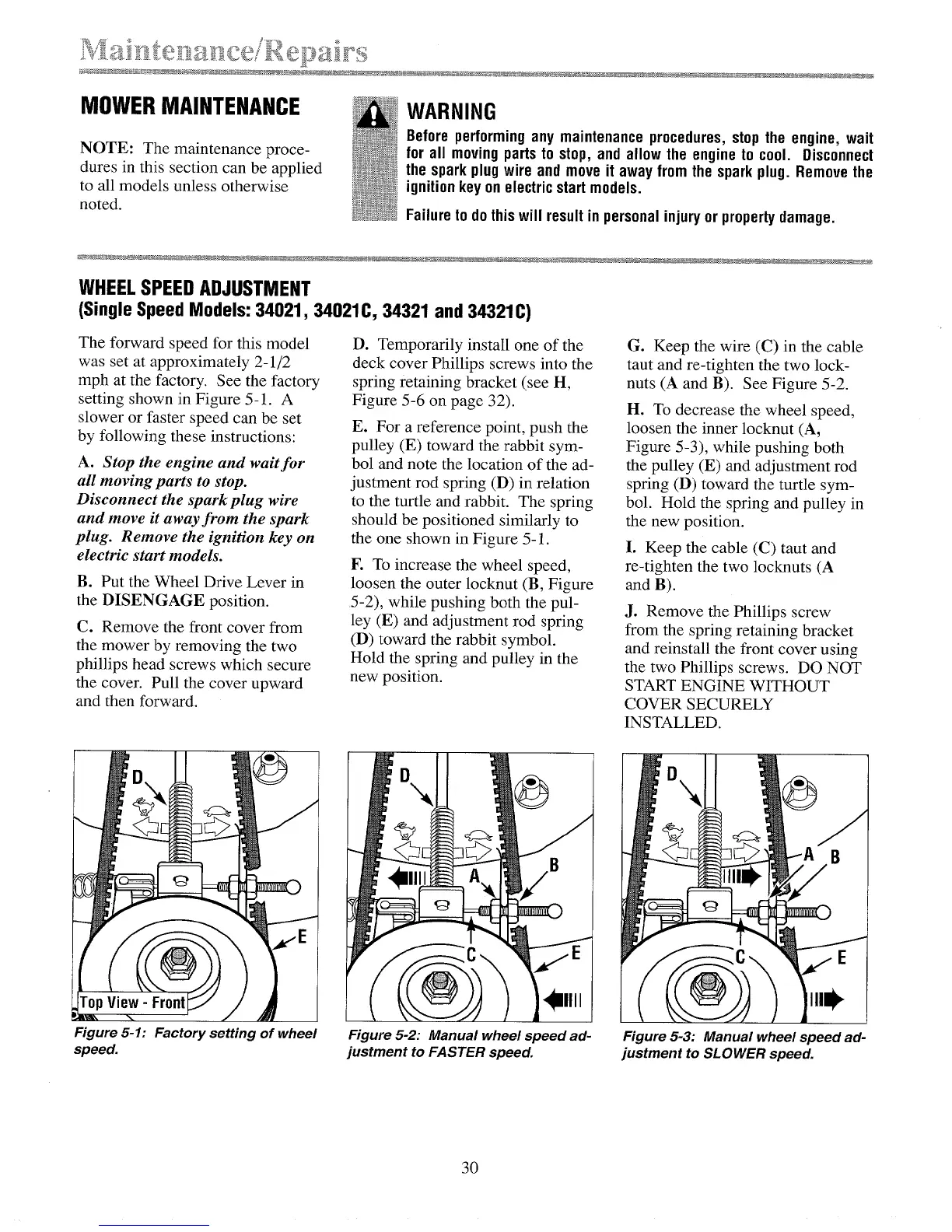
The forward speed for this model
was set at approximately 2-1/2
mph at the factory. See the factory
setting shown in Figure 5-1. A
slower or faster speed can be set
by following these instructions:
A. Stop the engine and wait for
all moving parts to stop.
Disconnect the spark plug wire
and move it away from the spark
plug. Remove the ignition key on
electric start models.
B. Put the Wheel Drive Lever in
the DISENGAGE position.
C. Remove the front cover from
the mower by removing the two
phillips head screws which secure
the cover. Pull the cover upward
and then forward.
Figure 5-1: Factory setting of wheel
speed.
D. Temporarily install one of the
deck cover Phillips screws into the
spring retaining bracket (see H,
Figure 5-6 on page 32).
E. For a reference point, push the
pulley (E) toward the rabbit sym-
bol and note the location of the ad-
justment rod spring (D) in relation
to the turtle and rabbit. The spring
should be positioned similarly to
the one shown in Figure 5-1.
F. To increase the wheel speed,
loosen the outer locknut (B, Figure
5-2), while pushing both the pul-
ley (E) and adjustment rod spring
(D) toward the rabbit symbol.
Hold the spring and pulley in the
new position.
Figure 5-2: Manual wheel speed ad-
justment to FASTER speed.
G. Keep the wire (C) in the cable
taut and re-tighten the two lock-
nuts (A and B). See Figure 5-2.
H. To decrease the wheel speed,
loosen the inner locknut (A,
Figure 5-3), while pushing both
the pulley (E) and adjustment rod
spring (D) toward the turtle sym-
bol. Hold the spring and pulley in
the new position.
I. Keep the cable (C) taut and
re-tighten the two locknuts (A
and B).
J. Remove the Phillips screw
from the spring retaining bracket
and reinstall the front cover using
the two Phillips screws. DO NOT
START ENGINE WITHOUT
COVER SECURELY
INSTALLED.
3O
Figure 5-3: Manual wheel speed ad-
justment to SLOWER speed.