OPERATINGMODELS34022,34022C, 34322 AND34322C
(VARIABLESPEEDWITH RECOILSTART)
STEP 1: General Starting
IMPORTANT: This model has
an Operator Presence Control
Bar which, if released during
mower operation, immediately
stops the engine, stops the
wheels, and stops the mower
blade within three seconds. Test
the operation of the Operator
Presence Control Bar before
each use of the mower. See the
Maintenance Section for this test
procedure.
WARNING
Before starting the engine
and after stopping the
mower, the Wheel Drive
Lever must be movedto the
DISENGAGE position. This
ensures that the mower will
not accidentally move for-
ward when the engine is
started.
Failure to do this couldresult
in personalinjury or property
damage.
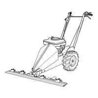
A. Move mower to a level area.
B. Connect the spark plug wire.
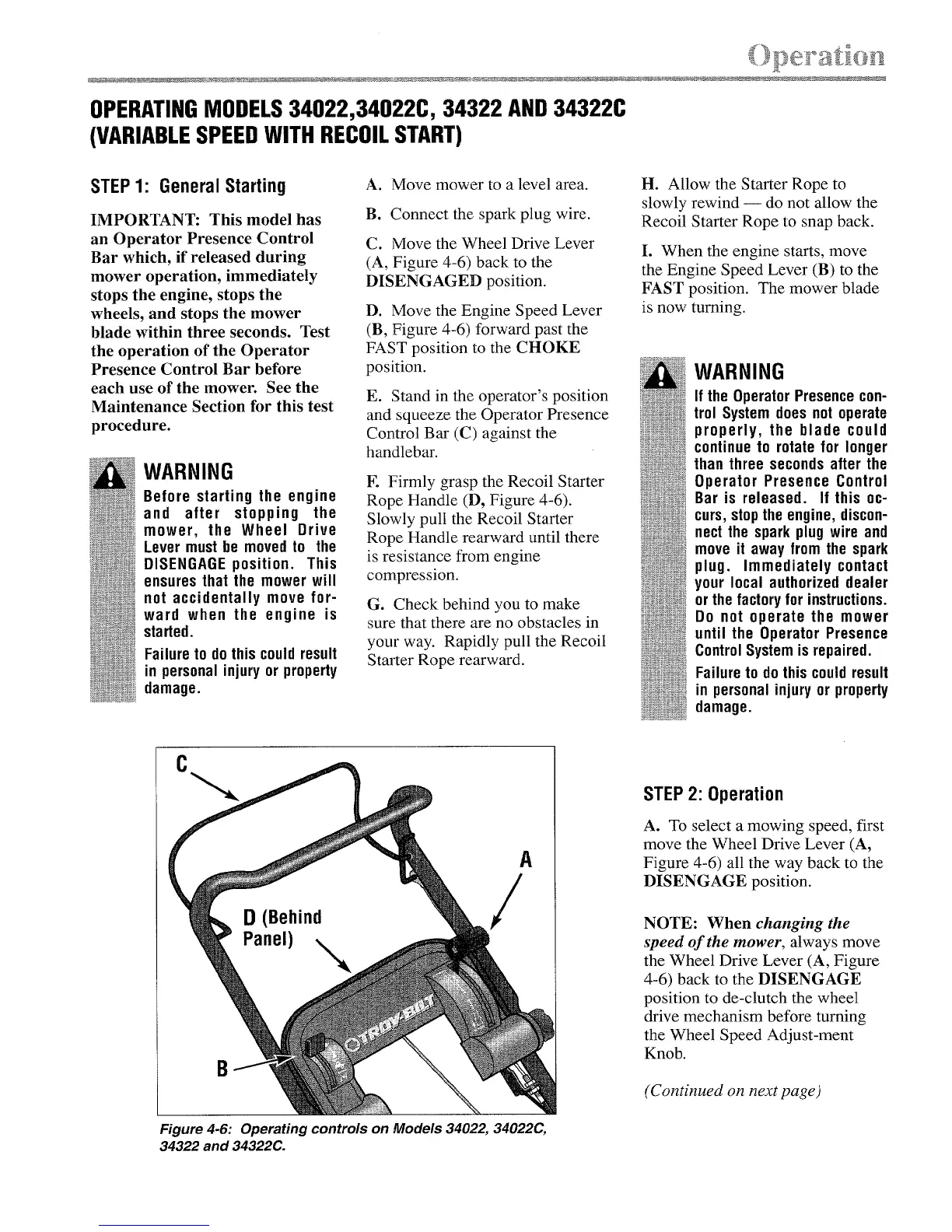
C. Move the Wheel Drive Lever
(A, Figure 4-6) back to the
DISENGAGED position.
D. Move the Engine Speed Lever
(B, Figure 4-6) forward past the
FAST position to the CHOKE
position.
E. Stand in the operator's position
and squeeze the Operator Presence
Control Bar (C) against the
handlebar.
E Firmly grasp the Recoil Starter
Rope Handle (D, Figure 4-6).
Slowly pull the Recoil Starter
Rope Handle rearward until there
is resistance from engine
compression.
G. Check behind you to make
sure that there are no obstacles in
your way. Rapidly pull the Recoil
Starter Rope rearward.
H. Allow the Starter Rope to
slowly rewind -- do not allow the
Recoil Starter Rope to snap back.
I. When the engine starts, move
the Engine Speed Lever (B) to the
FAST position. The mower blade
is now turning.
WARNING
If the OperatorPresencecon-
trol System does not operate
properly, the blade could
continue to rotate for longer
than three secondsafter the
Operator Presence Control
Bar is released. If this oc-
curs, stopthe engine, discon-
nectthe spark plug wire and
move it away from the spark
plug. Immediately contact
your local authorized dealer
orthe factoryfor instructions.
Do not operate the mower
until the Operator Presence
ControlSystemis repaired.
Failureto dothis couldresult
in personal injury or property
damage.
A
B
Figure 4-6: Operating controls on Models 34022, 34022(?,,
34322 and 34322C.
STEP 2: Operation
A. To select a mowing speed, first
move the Wheel Drive Lever (A,
Figure 4-6) all the way back to the
DISENGAGE position.
NOTE: When changing the
speed of the mower, always move
the Wheel Drive Lever (A, Figure
4-6) back to the DISENGAGE
position to de-clutch the wheel
drive mechanism before turning
the Wheel Speed Adjust-ment
Knob.
(Continued on next page)