WHEELTRACTIONADJUSTMENT(Allmodelsexcept PushModel)
WARNING
• Before performing any
maintenance procedures,
stop engine,wait for all mov-
ing parts to stop, and allow
engine to cool. Disconnect
spark plug wire and move it
away from spark plug.
Remove ignition key onelec-
tric startmodels.
• The wheel drive control on
the mower must function
properly or serious personal
injury and property damage
canresult. Do notoperatethe
mower if thewheel drive con-
trol does not properlyengage
and disengagethe wheels.
inspection
If the mower does not self-propel
when the wheel drive control is
engaged, first check for the
following two conditions:
1. Loss of wheel drive can occur
if moisture collects on the un-
derside of the mower or under
the front cover (especially after
washing the mower). Let the
mower dry thoroughly and then
start the engine. Raise the front
wheels slightly off the ground,
engage the wheels, and let the
wheels spin freely for about
two minutes before lowering
the wheels to the ground.
2. Inspect for grass or debris
build-up under the front deck
and under the front cover.
Refer to "Cleaning Under Deck
and Under Mower Cover" in
this Section for the procedure
to follow. Clean and dry these
areas thoroughly, reinstall the
cover, and test for proper wheel
drive. NOTE: While cover is
removed, check that belt is not
broken or excessively worn.
If performing the above checks
does not correct the problem, per-
form the "Initial Wheel Traction
Adjustment" described next.
Initial Wheel Traction
Adjustment
This procedure adjusts the tension
on the wheel drive cable.
A. Stop the engine and wait for
all moving parts to stop.
Disconnect the spark plug wire
and move it away from the spark
plug. Remove the ignition key on
electric start models.
B. Put the Wheel Drive Lever (or
the Wheel Drive Control Bar on
Models 34311, 34313 and 34328)
in the DISENGAGE position.
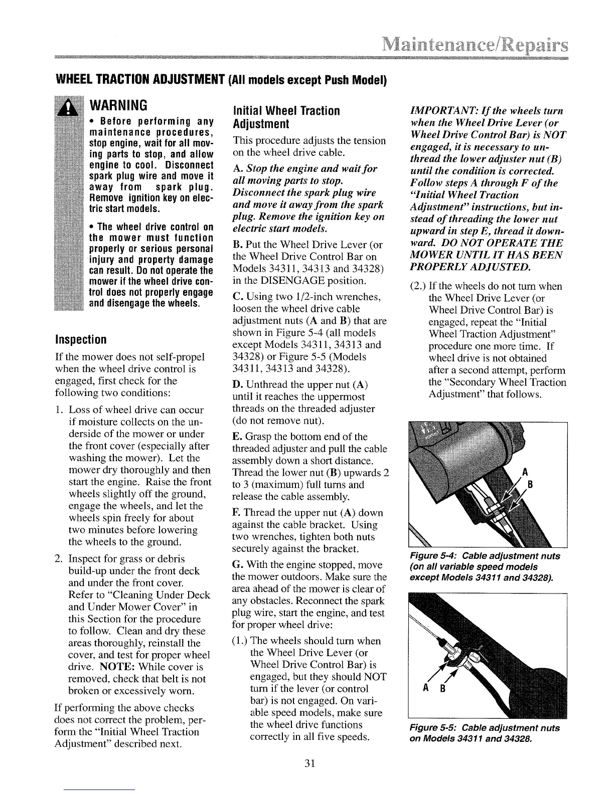
C. Using two 1/2-inch wrenches,
loosen the wheel drive cable
adjustment nuts (A and B) that are
shown in Figure 5-4 (all models
except Models 34311,34313 and
34328) or Figure 5-5 (Models
34311, 34313 and 34328).
D. Unthread the upper nut (A)
until it reaches the uppermost
threads on the threaded adjuster
(do not remove nut).
E. Grasp the bottom end of the
threaded adjuster and pull the cable
assembly down a short distance.
Thread the lower nut (B) upwards 2
to 3 (maximum) full turns and
release the cable assembly.
F. Thread the upper nut (A) down
against the cable bracket. Using
two wrenches, tighten both nuts
securely against the bracket.
G. With the engine stopped, move
the mower outdoors. Make sure the
area ahead of the mower is clear of
any obstacles. Reconnect the spark
plug wire, start the engine, and test
for proper wheel drive:
(1 .) The wheels should turn when
the Wheel Drive Lever (or
Wheel Drive Control Bar) is
engaged, but they should NOT
turn if the lever (or control
bar) is not engaged. On vari-
able speed models, make sure
the wheel drive functions
correctly in all five speeds.
IMPORTANT: If the wheels turn
when the Wheel Drive Lever (or
Wheel Drive Control Bar) is NOT
engaged, it is necessary to un-
thread the lower adjuster nut (B)
until the condition is corrected.
Follow steps A through F of the
"Initial Wheel Traction
Adjustment" instructions, but in-
stead of threading the lower nut
upward in step E, thread it down-
ward. DO NOT OPERATE THE
MOWER UNTIL IT HAS BEEN
PROPERLY ADJUSTED.
(2.) If the wheels do not turn when
the Wheel Drive Lever (or
Wheel Drive Control Bar) is
engaged, repeat the "Initial
Wheel Traction Adjustment"
procedure one more time. If
wheel drive is not obtained
after a second attempt, perform
the "Secondary Wheel Traction
Adjustment" that follows.
N,
Figure 5-4: Cable adjustment nuts
(on all variable speed models
except Models 34311 and 34328).
A B
Figure 5-5: Cable adjustment nuts
on Models 34311 and 34328.
31
 Loading...