(8.) Put the Wheel Drive Lever (or
Control Bar) in the ENGAGE
position and try to turn the
wheels. They should not turn.
If they do, thread the upper
and lower adjustment nuts
(Figures 5-4 or 5-5) upward 2
to 3 full turns. Repeat this
step as needed until the
wheels do not turn.
(9.) Reinstall the plastic thread
protector (C).
M. Remove the Phillips screw
from the spring retaining bracket
and reinstall the front deck cover
using the two Phillips head screws.
DO NOT START ENGINE
WITHOUT COVER SECURELY
INSTALLED.
N. With the engine stopped, move
the mower outdoors and make sure
the area ahead of the mower is
clear of any obstacles. Reconnect
the spark plug wire, start the en-
gine, and test for proper wheel
drive:
(1.) The wheels should turn when
the Wheel Drive Lever (or
Wheel Drive Control Bar) is
engaged, but they should NOT
turn if the lever (or control bar)
is not engaged. On variable
speed models, make sure the
wheel drive functions properly
in all five speed settings.
IMPORTANT: If the wheels turn
when the Wheel Drive Lever (or
Wheel Drive Control Bar) is NOT
engaged, readjust the mower by
repeating steps A through M. DO
NOT OPERATE THE MOWER
UNTIL IT HAS BEEN PROP-
ERLY ADJUSTED.
(2.) If the wheels do not turn when
the Wheel Drive Lever (or
Wheel Drive Control Bar) is
engaged, repeat steps A
through M.
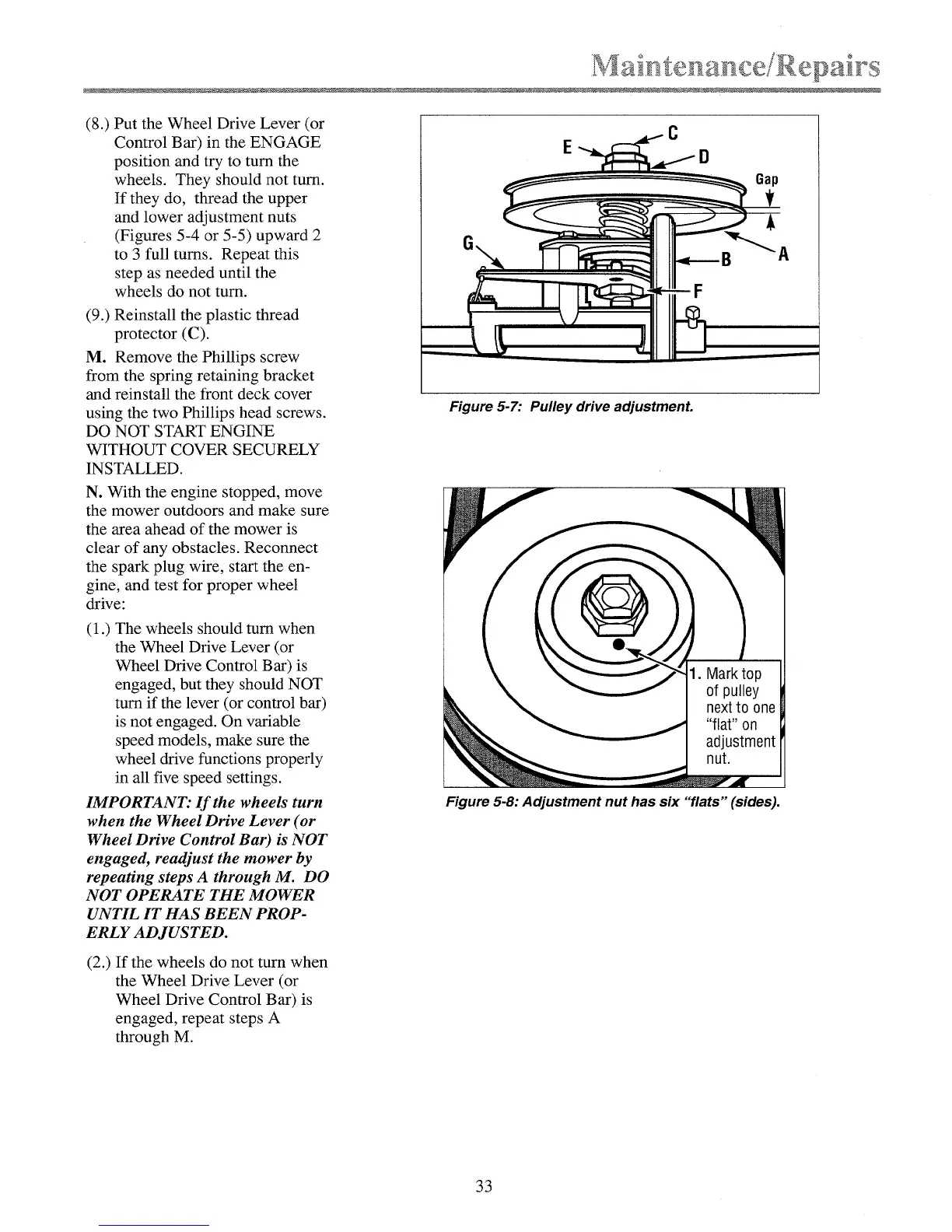
C
E D
Gap
Figure 5-7: Pulley drive adjustment.
Figure 5-8: Adjustment nut has six "flats" (sides).
33