PTO
HORSE
MODEL
TECHNICAL
MANUAL
Page
5-4
4/90
SECTION
5:
PTO
Power
Unit
Transmission
cannot
do
this
with
your
fingers,
insert a
long
bar
in
through
the
rear
of
the
housing
to
tap
the
bear-
ing
cup
out. Be careful
to
not
damage
the
inside
of
the
housing
or
the (internal) snap ring (21).
16.
The
(internal) snap ring (21)
can be removed (if necessary)
by
reaching
through
the
rear
of
the
transmission
with
snap ring pliers.
17.
The
front
and
rear drive
shaft
bearings (19) are
pressed-on
and can be removed (if necessary)
with
an
arbor
press and a bearing
puller
attachment.
After
removing
the
bearings, remove
the
shoulder
washers (22), if
so
equipped.
Inspection
These
instructions
describe
how
to
inspect
vital parts
on
the
PTO
power
unit
drive shaft. In
addition
to
inspecting
the
parts
you
have
removed,
you
should
also
inspect
any
replacement
parts
you
will
use.
Note:
Thoroughly
degrease and
clean all parts
before
inspection.
Drive
Shaft
-
1.
The
drive
shaft
should
not
be
scored, pitted,
or
corroded
where
the oil seals are located.
1<1
_-
•
If
shaft
i?5corelJ
•.
~ound
the
oil eal
are'
disccfr-d''the drive
shaft. .
I ' .
•
If
the
shaft
is
pitted
around
the
oil seal areas
you
may
be able
to
relocate
the
oil seals
to
a
smooth
area.
•
If
the
shaft
is
corroded
around
the
oil seal areas,
try
using
fine
(400
grit)
emery
cloth
to
clean
the
area.
2.
Before installing
the
drive
shaft
you
should
use 400
grit
emery
cloth
to
polish
the
shaft
up
to
and
including
the
keyways.
This
will prevent
cutting
of
the oil seals
when
they
are installed.
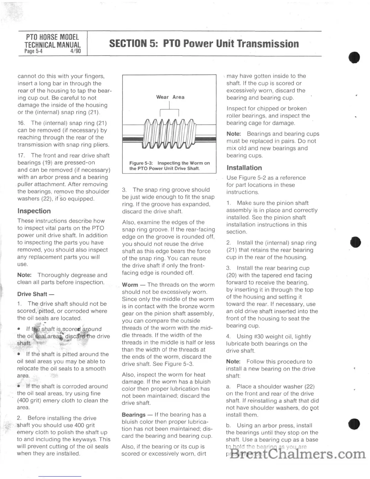
Wear Area
~
117'r
,"l~}
}-~
'I
v.J
t , "
'1;'"
Figure 5-3: Inspecting the
Worm
on
the PTO Power
Unit
Drive Shaft.
3.
The
snap ring
groove
should
be
just
wide
enough
to
fit the snap
ring. If the
groove
has expanded,
discard
the drive shaft.
Also,
examine
the edges
of
the
snap ring groove. If the rear-facing
edge
on
the
groove
is
rounded
off,
you
should
not
reuse the drive
shaft as this edge bears
the
force
of
the snap ring. You can reuse
the drive shaft if
only
the
front-
facing
edge is
rounded
off.
Worm
-
The
threads on
the
worm
should
not
be excessively worn.
Since
only
the
middle
of
the
worm
is in
contact
with
the
bronze
worm
gear
on
the
pinion
shaft assembly,
you
can
compare
the
outside
threads
of
the
worm
with
the
mid-
dle
threads. If the
width
of
the
threads in the
middle
is half
or
less
than the
width
of
the threads at
the ends
of
the
worm,
discard
the
drive shaft. See Figure
5-3.
Also, inspect
the
worm
for
heat
damage. If the
worm
has a bluish
color
then
proper
lubrication
has
not
been maintained; discard the
drive shaft.
Bearings
- If the bearing has a
bluish
color
then
proper
lubrica-
tion
has
not
been maintained;
dis-
card
the
bearing and bearing cup.
Also, if
the
bearing
or
its
cup
is
scored
or
excessively worn,
dirt
may
have
gotten
inside
to
the
shaft. If
the
cup
is
scored
or
excessively worn,
discard
the
bearing
and
bearing
cup.
Inspect
for
chipped
or
broken
roller
bearings, and
inspect
the
bearing cage
for
damage.
Note:
Bearings
and bearing
cups
must
be replaced in pairs.
Do
not
mix
old
and
new
bearings
and
bearing cups.
Installation
Use Figure 5-2 as a reference
for
part
locations
in these
instructions.
1.
Make
sure
the
pinion
shaft
assembly
is in place
and
correctly
installed. See
the
pinion
shaft
installation
instructions
in
this
section.
2.
Install
the
(internal)
snap
ring
(21)
that
retains
the
rear bearing
cup
in the rear
of
the
housing.
3.
Install
the
rear
bearing
cup
(20) with
the
tapered
end
facing
forward
to
receive
the
bearing,
by
inserting 'it in
through
the
top
of
the
housing
and
setting
it
toward
the
rear.
If
necessary, use
an
old
drive
shaft
inserted
into
the
front
of
the
housing
to
seat
the
bearing cup.
4.
Using
#30
weight
oil,
lightly
lubricate
both
bearings
on
the
drive shaft.
Note:
Follow
this
procedure
to
install a
new
bearing
on
the
drive
shaft:
a.
Place a
shoulder
washer
(22)
on
the
front
and rear
of
the
drive
shaft.
If
reinstalling a
shaft
that
did
not
have
shoulder
washers,
do
Clot
install them.
b.
Using
an
arbor
press, install
the
bearings
until
they
stop
on
the
shaft. Use a bearing
cup
as a base
to
hold
the
bearing as
you
are
pressing it on.