SECTION
5:
PTO
Power
Unit
Transmission
PTO
HORSE
MODEL
TECHNICAL
MANUAL
Page
5-7
4/90
Note:
Thoroughly
degrease and
clean all parts before inspection.
Bearings -
Hold
the end
of
the
stem pinion and spin the stem
pin-
ion bearing. If the bearing
wob-
bles,
or
makes a
growling
noise,
or
cannot spin at all, replace the
bearing with a new one. To test
the other bearing, pinch it by the
hole and spin it. If it wobbles,
or
makes a
growling
noise,
do
not
reuse it.
Stem Pinion - If the gear teeth
are broken
or
excessively worn,
discard the stem pinion.
Fast Speed Pinion Gear - If the
gear teeth are broken
or
exces-
sively worn, discard the gear. Also,
make sure the key is in
good
con-
dition
and
is
secure in the gear
keyway.
Bronze Worm
Gear
- If the gear
teeth are damaged
or
excessively
worn, discard the gear.
Side Plugs - Check the groove
where the
a-ring
seats; there
should be
no
burrs
or
sharp edges
to
cut
the
a-ring.
Use a fine file
or
400
grit
emery paper to smooth
any rough spots.
Make sure the
a-ring
grooves are
clean.
Dirt
or
debris will prevent
the
a-rings
from seating properly.
Transmission Housing - Make
sure the transmission housing has
no
burrs
or
sharp edges that
could
cut
the
a-ring
as
you install the
side plugs. Use a fine file
or
400
grit
emery paper
to
smooth any
rough spots.
Installation
Before
you
install the pinion shaft
assembly the wheel shaft assem-
bly
must first
be
in place. See the
wheel shaft installation instruc-
tions in this section.
Use Figure 5-4
as
a reference
for
part locations in these instructions.
1.
Attach the key
(12)
to
the
out-
side keyway in the fast speed pin-
ion gear (11). Make sure the key
does
not
obstruct the snap ring
groove.
2.
Attach the bronze
worm
gear
(10)
to the fast speed
pinion
gear
making sure the worm gear
hub
is
placed towards the fast speed pin-
ion gear. To attach, set the bronze
worm
gear on an open vise and
seat the fast speed gear with a
rubber mallet.
3.
Attach the (external) snap ring
(9)
to the fast speed pinion gear.
Make sure the rounded side of the
snap ring is facing towards the
fast speed gear.
Though
not
easy
to
observe, the snap ring has a flat
side and a rounded side.
4.
Using an open vise and a
rubber mallet, attach the washer
(8)
and bearing (7) to the left side
of
the stem pinion (5). If you are
using a sealed bearing, make sure
the seal faces out.
5.
Use #30 weight oil to lubricate
the
two
bearings (7).
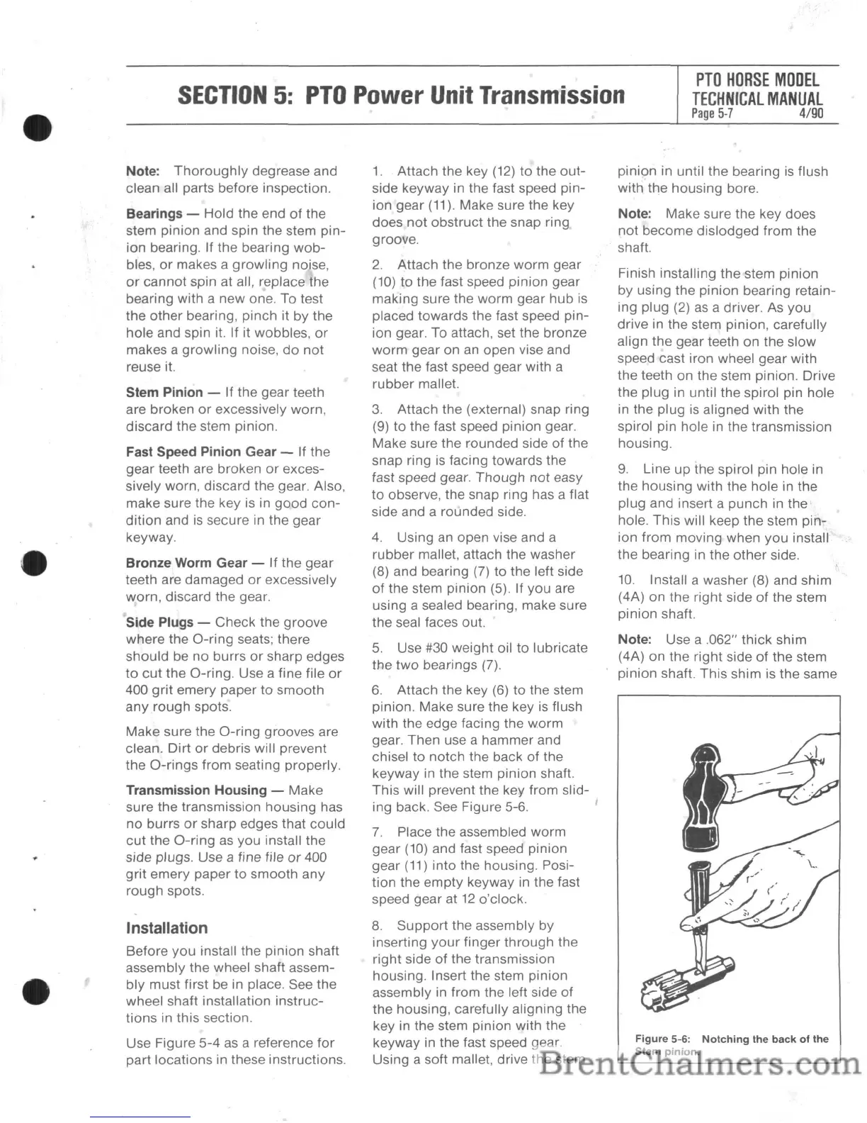
6.
Attach the key
(6)
to the stem
pinion. Make sure the key is flush
with the edge facing the
worm
gear. Then use a hammer and
chisel
to
notch the back of the
keyway in the stem pinion shaft.
This will prevent the key from slid-
ing back. See Figure 5-6.
7.
Place the assembled worm
gear
(10)
and fast speed pinion
gear
(11)
into the housing. Posi-
tion the
empty
keyway in the fast
speed gear at
12
o'clock.
8.
Support
the assembly by
inserting
your
finger
through
the
right side
of
the transmission
housing. Insert the stem pinion
assembly in from the left side
of
the housing, carefully aligning the
key in the stem pinion with the
keyway in the fast speed gear.
Using a soft mallet, drive the stem
pinion in until the bearing
is
flush
with the housing bore.
Note: Make sure the key does
not
become dislodged from the
shaft.
Finish installing the stem pinion
by using the
pinion
bearing retain-
ing plug (2)
as
a driver. As you
drive in the stem pinion, carefully
align the gear teeth on the slow
speed cast iron wheel gear with
the teeth on the stem pinion. Drive
the plug in until the spirol pin hole
in the plug is aligned with the
spirol pin hole in the transmission
housing.
9.
Line
up
the spirol pin hole in
the housing with the hole in the
plug and insert a punch in
the'
hole. This will keep the stem pin-
ion from moving when you install
the
bearing in the
other
side.
10.
Install a washer (8) and shim
(4A) on the right side
of
the stem
pinion shaft.
Note: Use a .062" thick shim
(4A) on the right side of the stem
pinion shaft. This shim is the same
Figure
5-6:
Notching
the
back
of
the
Stem
pinion.