PTO
HORSE
MODEL
TECHNICAL
MANUAL
Page
5-6
4/90
SECTION
5:
PTO
Power
Unit
Transmission
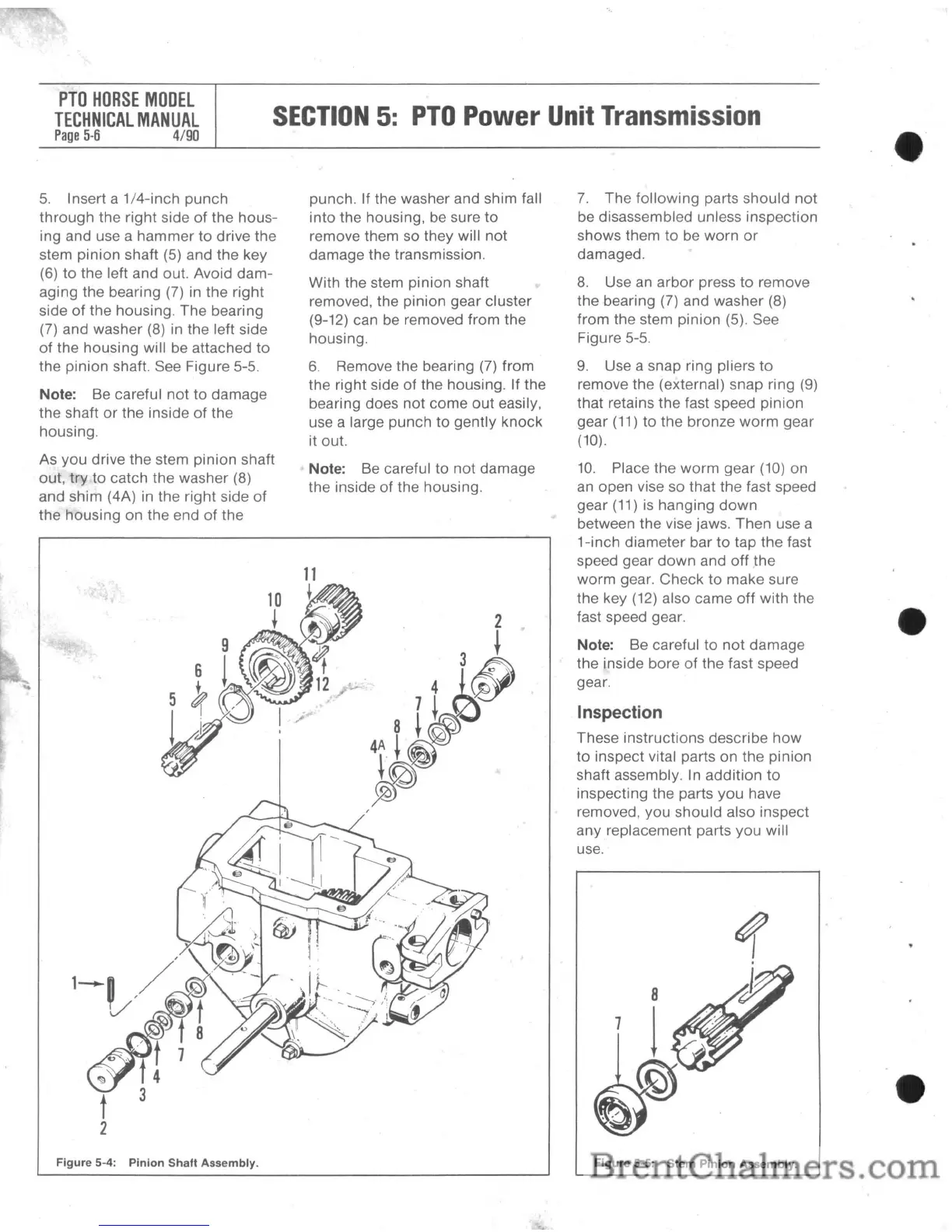
5.
Insert a
1/4-inch
punch
through
the right side of the
hous-
ing and use a
hammer
to
drive the
stem
pinion
shaft (5) and
the
key
(6) to the left and out. Avoid
dam-
aging the bearing (7) in the right
side
of
the housing. The bearing
(7) and washer (8) in the left side
of the housing will be attached
to
the
pinion
shaft. See Figure 5-5.
Note: Be careful
not
to
damage
the shaft
or
the inside of the
housing.
As you drive the stem pinion shaft
out,
try
to
catch the washer
(8)
and shim (4A) in the
right
side
of
the housing on the end
of
the
Figure 5-4: Pinion Shaft Assembly.
punch. If the washer and shim fall
into
the housing, be sure
to
remove them so they will
not
damage the transmission.
With the stem pinion shaft
removed, the pinion gear cluster
(9-12) can be removed from the
housing.
6.
Remove the bearing (7) from
the right side
of
the housing. If the
bearing does not
come
out
easily,
use a large
punch
to
gently
knock
it out.
Note: Be careful
to
not damage
the inside of the housing.
7.
The
following
parts
should
not
be disassembled unless inspection
shows them to be
worn
or
damaged.
8.
Use an
arbor
press
to
remove
the bearing
(7) and washer (8)
from
the stem pinion (5). See
Figure
5-5.
9.
Use a snap ring pliers
to
remove the (external) snap ring (9)
that retains the fast speed
pinion
gear
(11)
to
the bronze
worm
gear
(10).
10.
Place the
worm
gear
(10)
on
an open vise so that the fast speed
gear
(11)
is
hanging
down
between the vise jaws.
Then
use a
1-inch diameter bar
to
tap the fast
speed gear
down
and
off
the
worm
gear.
Check
to
make
sure
the key
(12)
also came
off
with the
fast speed gear.
Note: Be careful
to
not
damage
the inside bore
of
the fast speed
gear.
Inspection
These instructions describe
how
to
inspect vital parts on the pinion
shaft assembly. In
addition
to
inspecting the parts
you
have
removed, you
should
also inspect
any
replacement parts you will
use.
Figure 5-5: Stem Pinion Assembly.