PTO
HORSE
MODEL
TECHNICAL
MANUAL
Page
6-1
4/90
SECTION
6:
Tiller
Attachment
Transmission
This section describes the
the procedures for servicing
the tiller attachment
transmission.
A
WARNING:
When servicing the machine, prevent uninten-
tional starting
of
the engine by disconnecting the spark plug
wire and keeping the wire away from the spark plug. Place
the engine throttle control
in
the
OFF
position and shift the
Wheels/Tines/PTa Drive Lever into NEUTRAL.
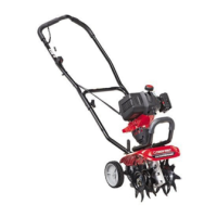
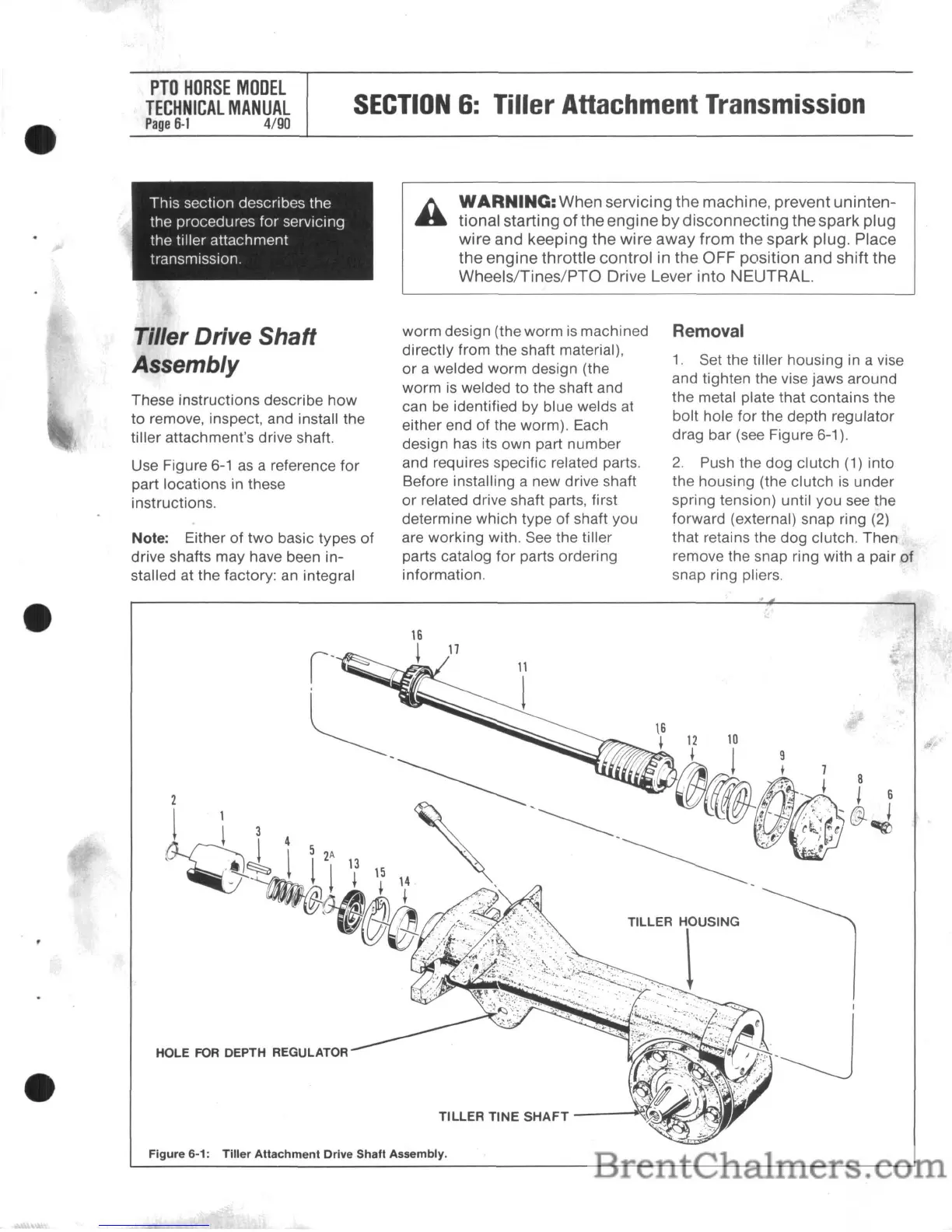
Tiller Drive Shaft
Assembly
These instructions describe how
to remove, inspect, and install the
tiller attachment's drive shaft.
Use Figure
6-1
as
a reference for
part locations in these
instructions.
Note: Either of
two
basic types
of
drive shafts may have been in-
stalled at the factory:
an
integral
HOLE
FOR
DEPTH REGULATOR
worm design (the worm
is
machined
directly from the shaft material),
or
a welded worm design (the
worm
is
welded to the shaft and
can be identified by blue welds
at
either end of the worm). Each
design has its own part number
and requires specific related parts.
Before installing a new drive shaft
or
related drive shaft parts, first
determine which type of shaft you
are working with. See the tiller
parts catalog
for
parts ordering
information.
TILLER
TINE
SHAFT
-el
Removal
1.
Set the tiller housing in a vise
and tighten the vise jaws around
the metal plate that contains the
bolt hole for the depth regulator
drag bar (see Figure 6-1).
2.
Push the dog clutch (1) into
the housing (the clutch
is
under
spring tension) until you see the
forward (external) snap ring (2)
that retains the dog clutch. Then
remove the snap ring with a pair
of
snap ring pliers.
Figure 6-1:
Tiller
Attachment Drive Shaft Assembly.
 Loading...