4
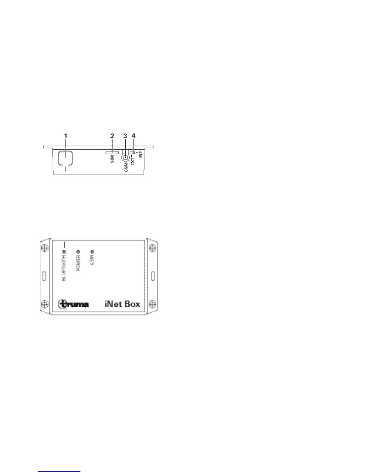
Rear view
1 BLUETOOTH / factory settings button
2 Mini-SIM (25 x 15 mm)
3 External antenna connection GSM (SMA)
4 Changeover switch, internal / external antenna GSM
Displays
Top view
Blue LED (BLUETOOTH pairing status)
Green LED (POWER lights up during operation)
Red LED (GSM) lights up when GSM operation is not possible.
Selecting a location
Install the iNet Box in a location that is protected from mois-
ture and humidity. For optimum transmission and reception,
secure the iNet Box as high up as possible, e.g. above a win-
dow and in the middle of the vehicle. At the same time, due
to the position of the installed antennae, the connections
should go upwards or downwards (secure the box perpendic-
ular on the wall).
The slot for the Mini-SIM and the external GSM antenna
connection, the internal / external antenna changeover
switch and the button for the BLUETOOTH pairing must
remain accessible.
Connect the external GSM antenna
People must maintain a distance of at least 20 cm from the
antenna.