23
Cold air distribution and circulated air
return
Air distribution
The same ducts (cold air ducts) are used for heating /
cooling mode.
A cold air duct KR 65 Ø 65 mm (10) with at least one outlet must
be connected to all three cold air outlets of the device (7, 8 + 9).
Slide the cold air ducts (10) into the cold air outlets of the
device and route to the air outlet nozzles. Ensure that the cold
air ducts are firmly seated in the cold air outlets. For noise
reduction purposes, Truma can supply a sound muffler for in-
stalling in the cold air system (part no. 40040-60100).
The swivel air outlet SCW 2 (black – part no. 39971-01 or beige –
part no. 39971-02), the end outlet EN-O (part no. 40171-07) with
lamella inset LA (part no. 40721-01/02/03/04/05) or the rectan-
gular air outlet RL (part no. 40280-01) with connector piece ANH
(part no. 40290-02) would be suitable as an outlet for the air into
the vehicle interior.
Important notes
The cold air distribution is designed individually using the
modular principle for each vehicle model. A wide range of ac-
cessories is available for this purpose.
In order achieve the maximum cooling power we recommend:
– Route cold air ducts to air outlet nozzles as short and
straight as possible.
– The total accumulated length of cold air duct that may be
used is 15 m.
– Connect the longest cold air duct (max. 8m) to the right-
hand cold air outlet (9), since this has the highest air
throughput.
– In order to avoid condensation, do not route the cold air
ducts in the vicinity of inflowing outside air (or behind the
refrigerator).
Circulated air return
The circulated air is drawn in again by the device, either via an
additional rectangular air grille (1 – part no. 40040-29200) or
through 3 round air grilles (part no. 40040-20400) e. g. in the
stowage box wall, or via several small openings with a total
area of at lest 300 cm².
Important note
The ventilation from the vehicle interior to the installation
area must be in the immediate vicinity of the equipment to
provide perfect air exchange. Covers must be fitted if neces-
sary to prevent the circulated air return from being affected by
stowed objects.
If installation in close proximity is not possible, Truma
can provide a flexible room air intake as an accessory
(part no. 40090-59100).
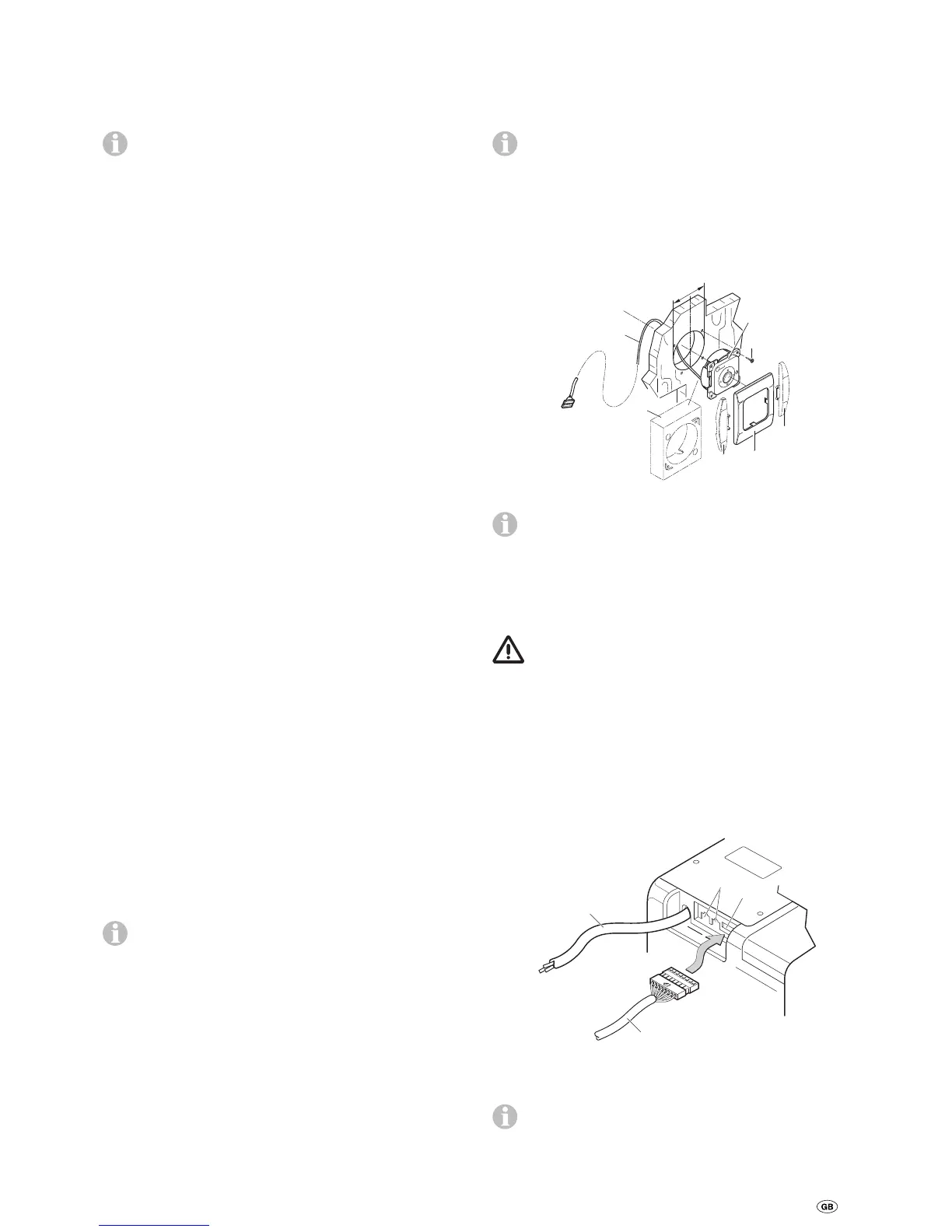
Installing the IR receiver
The receiver (12) should preferably be mounted to the ward-
robe in such a way that the remote control can be pointed at it
without obstructions (length of connecting cable 3 m). A 3 m
cable extension is available if necessary (part no. 40090-89100).
If the receiver cannot be flush-mounted, Truma can sup-
ply an on-surface frame (13) – part no 40000-52600 – as
an accessory on request.
Drill Ø 55 mm hole. Lead IR receiver cable (17) through hole
towards the rear and secure receiver with 4 screws (14 – not
included in scope of delivery). Then fit cover frame (15) and
route cable (17) to air conditioning system.
Ø 55 mm
16
16
15
13
12
14
17
Fig. 17
To finish off the cover frame, Truma can supply side
parts (16) in 8 different colours as an accessory (please
ask your dealer).
230 V electrical connection and
connection of IR receiver
The 230 V electrical connection must always be made
by an expert (in accordance with VDE 0100, part 721 or
IEC 60364-7-721, for example, in Germany).The instructions
shown here do not constitute a request to non-experts to
make the electrical connection, but serve as additional infor-
mation for an expert who is employed to do the work!
Make the connection to the mains via the 150 cm long con-
nector cable (20) to a line that is protected with a 10 A fuse in
the vehicle.
It is imperative that connection is carried out with care while
observing the correct cable colours!
20
18
19
17
Fig. 18
Plug connector of IR receiver cable (17) into the socket (19).
The connection (18) is a Com connection for commu-
nication purposes, and is not needed to operate the
device.

 Loading...