14 PhenoMaster | Hardware Operating Instructions
Drinking and Feeding measurements
• The drinking and feeding sensors can be used with the dispensers supplied by TSE only - if
others are used, measuring errors will occur.
• (Re)assembly of rod drinking nipples
NOTICE - Dehydration hazard!
If the O-ring of the valve rod is positioned in the false orientation, flow through the opening of
the extension cap is always blocked and animals can die of thirst.
• Position O-ring onto the gasket so that its smaller base is orientated towards the gasket.
• After (re)assembly, always perform a test to ensure that liquid can flow throughout the nipple.
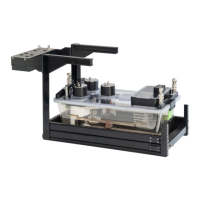
Fig. 3 Hardware layout - Rod nipple
1 Nipple receiver
2 O-ring, NBR (nipple receiver)
3 Valve rod
4 Gasket
5 O-ring, rubber (valve rod)
6 Pressure spring
7 Extension cap
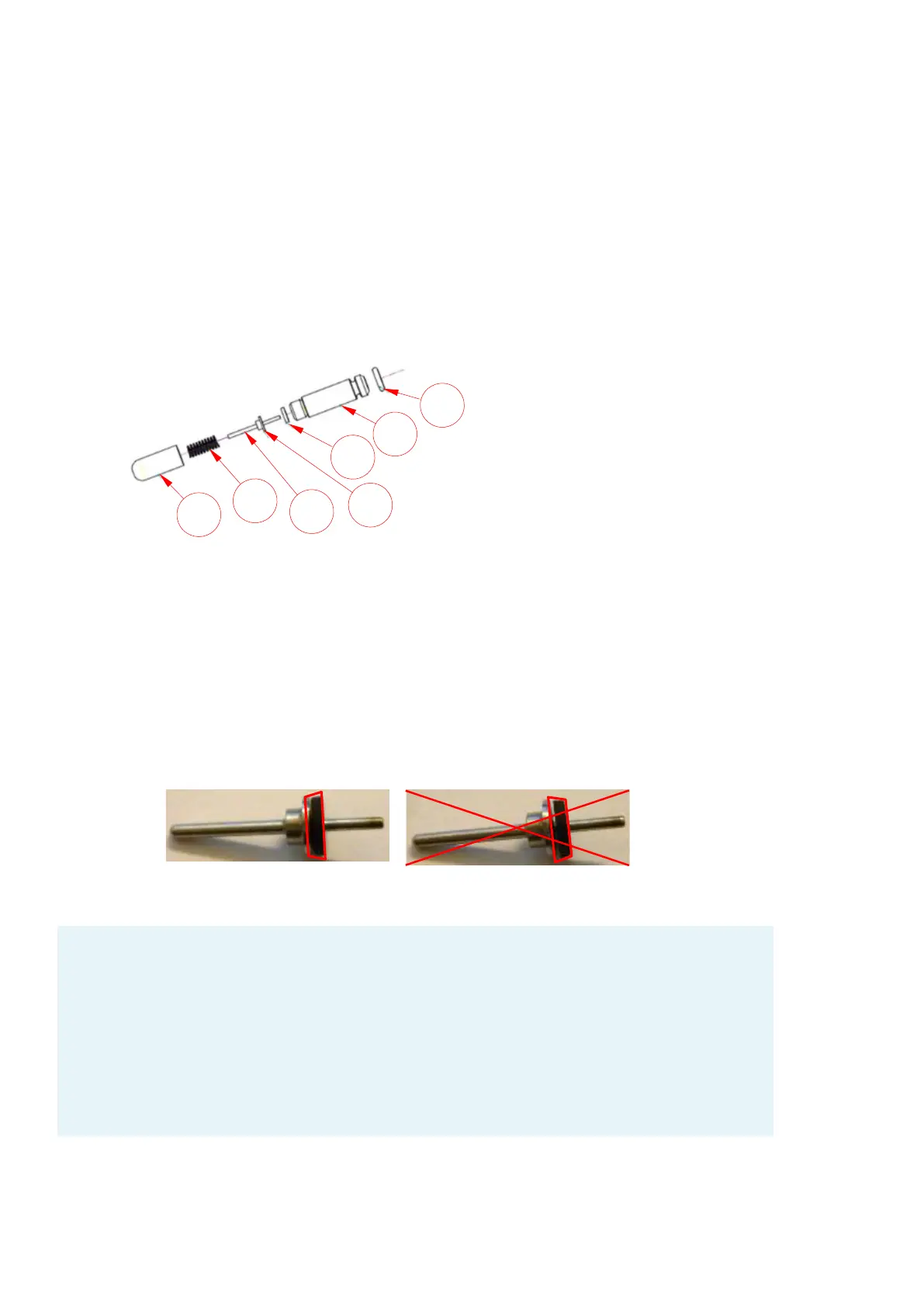
o Position O-ring (valve rod) onto gasket (shorter end of valve rod). The smaller base of
the O-ring must be orientated towards the gasket, as otherwise flow through the
opening of the extension cap is always blocked and animals can die of thirst!
Fig. 4 Positioning of O-ring (valve rod)
How to test the operability, i.e. flowability, of the drinking nipple?
• Fill dispenser with water.
• If not already done, attach drinking cap including nipple.
• Suspend dispenser from sensor.
• Wait approx. 20s until water and air are in equilibrium.
• With a moistened finger, touch the tip of the nipple slightly (thereby moving the valve
rod to the side). It should be possible to "pull off" a drop. If not, a check for potential
sources and remedies, respectively, has to be made.
info@TSE-Systems.com www.TSE-Systems.com