Version 1.7 (June 2017)
TSI Flowmeters Ltd.
1.4
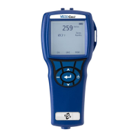
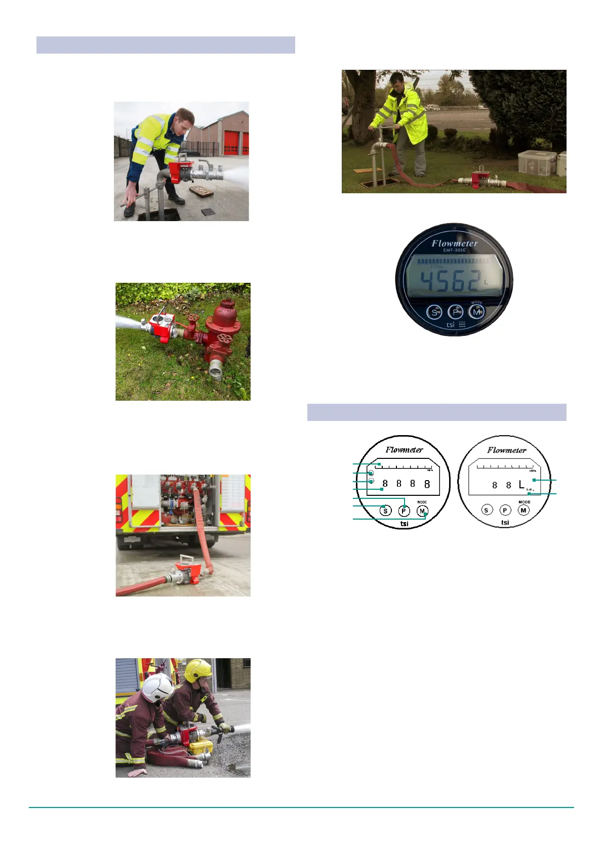
Fig. 1.8 User panel explanation
(1) Bar graph display of ow reading
(2) Digit display of ow reading
(3) Set / Select switch
(4) Plus switch used to increment setting in calibration
mode
(5) Mode / Minus switch:
Mode - selects between ow and totaliser operating
modes
Minus - decrements setting in calibration mode
(6) Indicates totaliser mode and volume
(7) Totaliser range extender:
No. Display Total as displayed
X 10 Multiply displayed volume by 10 to
get total
X 100 Multiply displayed volume by 100 to
get total
(8) Flashes on and off to indicate there is no water in
the sensor
(9) Flashes on and off to indicate there may be dirt on
the electrodes. Ignore this signal when there is no
water in the sensor
(1)
(8)
(9)
(2)
(3)
(5)
(6)
(4)
(7)
EXPLANATION OF USER PANEL
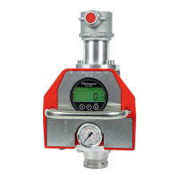
1.3 APPLICATIONS
Fig. 1.3 Testing pillar re hydrants on high pressure ring
main
Fig. 1.4 Testing re pump
Fig. 1.5 Testing a new branch
Fig. 1.2 Testing underground re hydrants
MEASURING STATIC AND DYNAMIC
PRESSURE AND FLOW RATE
USING THE FLOWMASTER TO TEST A FIRE
HYDRANT
USING THE FLOWMASTER TO TEST A FIRE
PUMP
1.3.2
1.3.1
1.3.3
USING THE FLOWMASTER TO TEST FIRE
FIGHTING EQUIPMENT
1.3.4
5
Fig. 1.6 Flushing
USING THE FLOWMASTER TO CONTROL
FLOW VELOCITY DURING FLUSHING.
1.3.5
Fig. 1.7 Use totalise function of Flowmaster to record
volume released during ushing for input to leakage
gure records
FLOW TOTAL