Home
TSi Power
Switch
ATS-800 Series
Page 11
TSi Power ATS-800 Series - Page 11
32 pages
Manual
Save Page as PDF
To Next Page
To Next Page
To Previous Page
To Previous Page
Loading...
TSi Power Corporation
MC80043,
4,5,6,7,8,9
,50
ATS-800 Series Automatic Transfer Switches
Rev. 3, April, 2018
TSi Power Corporation Proprietary Info
rmation
11
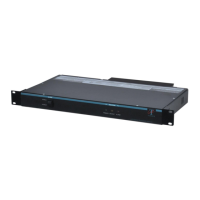
Figure 8:
Top
-Down Rear view showing Hardwired ATS-800
with top-cover
removed
Primary
AC
Input
Compartment
Backup 15
A
,
20 A, 30 A or
40 A Circuit
Breaker
Compartment
Cover M
ounting
Holes
Primary 15
A
, 20
A,
30 A or 40
A
Circuit Breaker
AC Output
Compartment
DB
-9
A
larm
Signal Output
Connector
/
Circuit Board
PZ00120 Main
Control
Circuit Board
Backup AC
Input
Compartment
Four Snap-On
Standoffs and one
Screw to M
ount
Circuit Board
Hardwire
Compartment
Cover
10
12
Table of Contents
Main Page
Default Chapter
2
Table of Contents
2
1 General
5
Product Application
5
Safety Alerts
6
General ATS Series Description
6
Overall Dimensions
7
Construction
8
Rear Access
8
Component Locations
10
2 Major Component/Circuit Descriptions
12
ATS Series System Architecture
12
ATS Circuit Boards
12
Input / Output Circuit Breakers
16
Audible Alarm Switch
16
3 Installation
16
Site Selection & Preparation
16
Required Tools
17
Unpacking & Inspection
17
Voltage Selection
17
Installing the ATS-800 Series
18
AC Connections (Hardwire Versions)
18
4 Powering up the Ats Series
20
Start-Up & Functional (Electrical) Test Procedure
20
Testing W/Actual Load Equipment (Computer)
21
Remote Status / Alarm Monitoring
21
Remote Enable Function
21
5 Repairs & Service
22
ATS Series Field Repair (Recommended Replacement Parts)
22
Returning Defective Circuit Board(S) for Repair
22
Inventory Recommendations for Customer W/Large Numbers of ATS
22
Units
22
6 Reference
23
Specifications
23
Product Configurations
31
Tsi Power Contact Information
32
Related product manuals
TSi Power ATS-500 Series
31 pages
 Loading...