Do you have a question about the Tsonic TUF-2000 Series and is the answer not in the manual?
Details the components making up the ultrasonic flow meter.
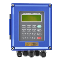
Lists and illustrates various converter models available for the flow meter.
Illustrates separated mounting arrangements for converters and transducers.
Provides alternative separated mounting configurations for the equipment.
Shows examples of fixed mounting installations for the flow meter system.
Instructions for setting up converters in a separated mounting configuration.
Installation and wiring guidance for TUF-2000S and TUF-2000D converter models.
Details the installation and wiring procedures for the TUF-2000U converter.
Provides instructions for the fixed mounting method of converter installation.
Details the installation and wiring procedures for the TUF-2000F2 converter.
Explains the installation process for converters using the module type method.
Details the introduction, features, and wiring of clamp-on type transducers.
Covers the introduction, components, and wiring for insertion type transducers.
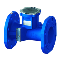
Explains the introduction, connection, and wiring of inline type transducers.
Describes the LCD display and the functions of the 16-key and 4-key keyboards.
Provides methods for navigating menus and operating the flow meter.
Detailed explanations of various menu options and their functions.
Step-by-step guide for quickly configuring essential measurement parameters.
Factors and guidelines for selecting optimal installation locations for transducers.
Detailed steps for installing clamp-on type transducers on pipelines.
Comprehensive guide for installing insertion type transducers in pipes.
Procedures for installing inline type transducers using companion flanges.
Methods for verifying the correctness of transducer installation and signal quality.
| Model | TUF-2000 Series |
|---|---|
| Type | Ultrasonic Flow Meter |
| Communication | RS485, Modbus |
| Accuracy | ±1% of reading |
| Pipe Size Range | DN15~DN6000 |
| Fluid Types | Water, Oil, Chemicals, etc. |
| Pressure Range | Up to 1.6 MPa (depending on transducer type) |
| Output | 4-20mA, Pulse, Relay |
| Protection Level | IP65 |
| Measurement Principle | Time Difference Method |