5. CONNECTORS AND PINS
Pin no./Shield Name (100BASE-T1) Name (100BASE-TX)
(Coding A)
1 BRR-TRX-P ETH_TX+
2 Not connected ETH_RX-
3 BRR-TRX-N ETH_TX-
4 Not connected ETH_RX+
Shield Not connected SHIELD
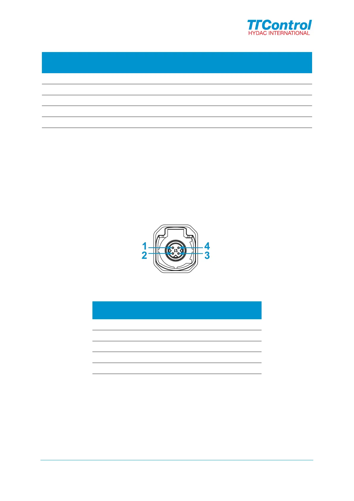
5.4 USB OTG connector (B) and USB HOST connector (D)
The USB OTG is supported by all products of the Vision 312 family.
The USB HOST is supported by Vision 312Plus products.
The connectors B and D are color-coded brown.
Mates with: Rosenberger D4K14A-1D5A5-F
Figure 6: Connector D pinout
Pin no./Shield
(Coding F)
Name
1 USB D+
2 USB VBUS
3 USB D-
4 USB GND
Shield SHIELD
5.5 Connector (C)
Reserved for future use.
© TTControl GmbH 2020. All rights reserved.
Confidential and Proprietary Information
16
Document Number:
D-156-G-02-001