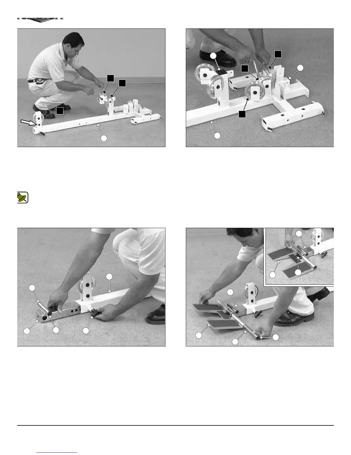
IG. 4 On a flat surface, lay the Base Frame (#2) down and attach
ree Pulleys 4 1/2 Rd (#68-Labeled D1,E1,E3) to the Base Frame (#2)
ing three Hex Head Cap Screws 3/8-16 X 2 (#109), six Flat Washers
AE 3/8” (#91), and three Nylon Insert Jam Lock Nuts 3/8-16 (#101).
ext, affix one Hex Head Cap Screw 3/8-16 X 2 (#109), two Flat
ashers SAE 3/8” (#91), and one Nylon Insert Jam Lock Nut 3/8-16
101) to the bracket in front of the Base Frame (#2).
Note: The black boxed letters pointing to the pulleys are used
throughout this manual as reference to the Cable Mapping
Diagrams on pages 24 - 39. These black boxed letters will be
primarily used for locating certain pulleys during the cable
routing process.
IG. 6 Insert the Low Row Stabilizer (#14) into the receptacle of
e Base Frame (#2). Next, using a rubber mallet, insert two Plastic
sert Caps 1” Rd. (#89) into the tube-ends of the Low Row Stabilizer
14).
FIG. 5 Using a rubber mallet, insert two Plastic Insert Caps 2” S
(#85) into the tube-ends of the Base Frame (#2). Next, attach thre
Pulleys 4 1/2 Rd (#68-Labeled A3,D2,F2) to the pulley brackets of th
Base Frame (#2) using three Hex Head Cap Screws 3/8-16 X 1 3
(#110), six Flat Washers SAE 3/8” (#91), and three Nylon Insert Ja
Lock Nuts 3/8-16 (#101).
FIG. 7 Using a rubber mallet, insert two Plastic Insert Caps 1” R
(#89) into the tube-ends of the Foot Roll Tube 1X16 (#31). Next, co
nect the Low Row Foot Support (#15) to the Low Row Stabiliz
(#14) using the Foot Roll Tube 1 X 16 (#31). Secure the Foot Ro
Tube 1X16 (#31) to the Low Row Stabilizer (#14) using one S
Screw 3/8-16 X 1/2 (#69), as shown in caption above.
3
D2
2
2
85
F2
85
E3
D1
A3
D2
74
2
14
89
89
15
31
89
14
14
69
15
AP-250S_AP-250D Apollo 2-Stack Gym Syste