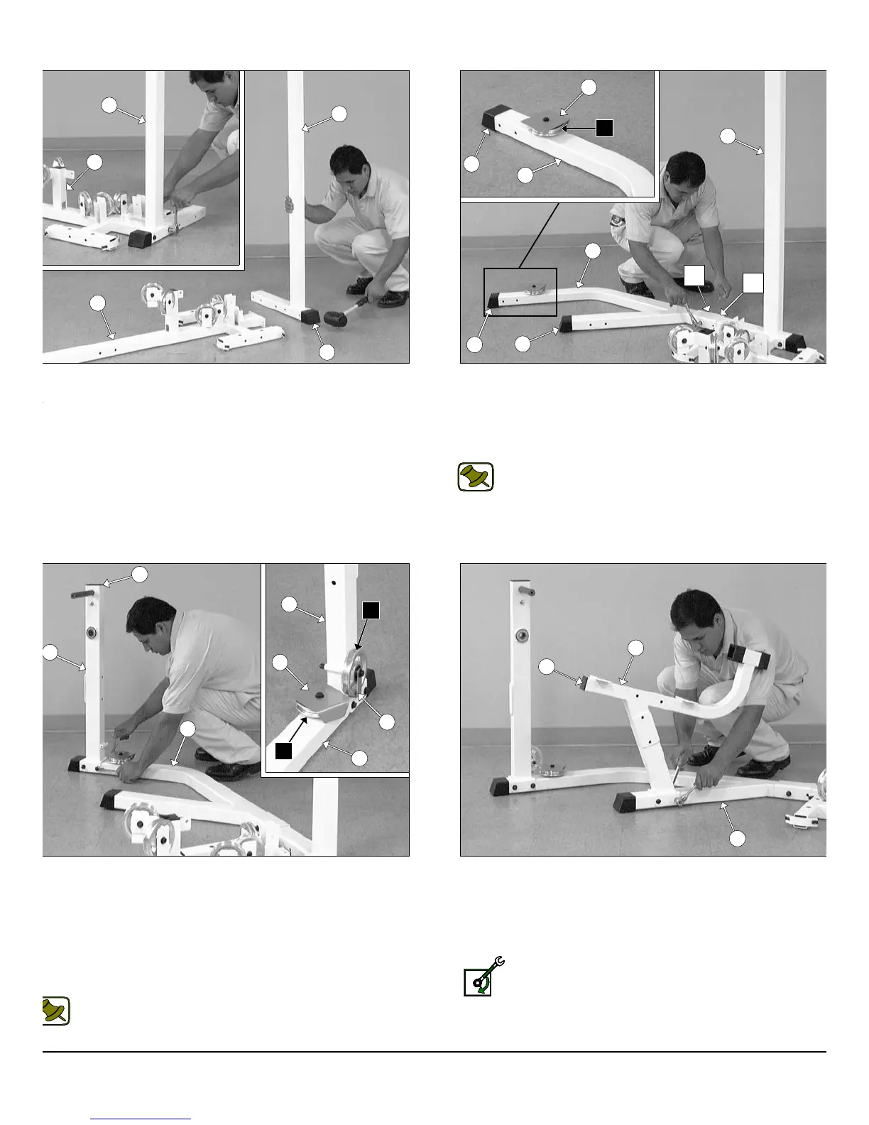
IG. 8 Using a rubber mallet, insert one Plastic Insert Cap w/ Groove
X 3 (#57) onto the tube-end of Rear Upright (#4). Next, attach the
ear Upright (#4) to the Base Frame (#2) using two Hex Head Cap
crews 3/8-16 X 4 (#105), four Flat Washers SAE 3/8” (#91), and two
ylon Insert Lock Nuts 3/8-16 (#100).
IG. 10 Next, attach the Leg Extension Front Frame (#11) to the
g Extension Main Frame (#9) using two Hex Head Cap Screws 3/8-
X 4 1/4 (#104), four Flat Washers SAE 3/8” (#91), and two Nylon
sert Lock Nuts 3/8-16 (#100). Next, attach one Pulley 4 1/2 Rd. (#68-
beled A1) and one Cable Retainer L-Shaped Bracket (#28) to the
g Extension Front Frame (#11) using one Hex Head Cap Screw
8-16 X 4 1/4 (#105), one Flat Washer SAE 3/8” (#91), and one Nylon
sert Lock Nut 3/8-16 (#100). Refer to Fig. 86 on page 30 for further
ustration of this hardware assembly.
Note: Be sure the Cable Retainer L-Shaped Bracket (#28) is
positioned as shown in caption above.
FIG. 11 Using a rubber mallet, insert one Plastic Insert Cap 2” S
(#85) into the tube-end of the Leg Extension Seat Frame (#12).Ne
attach the Leg Extension Seat Frame (#12) to the Leg Extensio
Main Frame (#9) using two Hex Head Cap Screws 3/8-16 X 4 1
(#104), four Flat Washers SAE 3/8” (#91) and two Nylon Insert Lo
Nuts 3/8-16 (#100).
Loosely Fasten: Do not completely fasten this hardwa
assembly at this time, as it will be completely fastened later i
the assembly process.
4
wner
s
anua
:
ssem
y
nstruct
on
4
2
4
2
57
57
50
9
57
57
9
4
A2
11
11
28
9
A1
A2
84
50
9
85
12
9
2
nd
1
st
FIG. 9 Using a rubber mallet, insert two Plastic Insert Caps
Groove 2 X 3 (#57) onto the tube-ends of the Leg Extension Mai
Frame (#9). Next, attach one Pulley 4 1/2 Rd. (#68-Labeled A2) an
one Pulley Cover Plate (#50) to the Leg Extension Main Frame (#
threaded socket using one Hex Head Cap Screw 3/8-16 X 1 3/4 (#110
one Split Lock Washer 3/8” (#95), and one Flat Washer SAE 3/8” (#91
Note: Attach the Leg Extension Main Frame (#9) to the Re
Upright (#4) using ONLY the 1
st
hole with one Hex Head C
Screw 3/8-16 X 4 1/4 (#104), two Flat Washers SAE 3/8” (#9
and one Nylon Insert Lock Nut 3/8-16 (#100). The other Bolt w
be installed in the 2
nd
hole once the Weight Shrouds (#22) ha
been assembled onto the unit. Refer to Fig. 82 on page 23 f
further clarification of this assembly.
P-250S_AP-250D Apollo 2-Stack Gym System