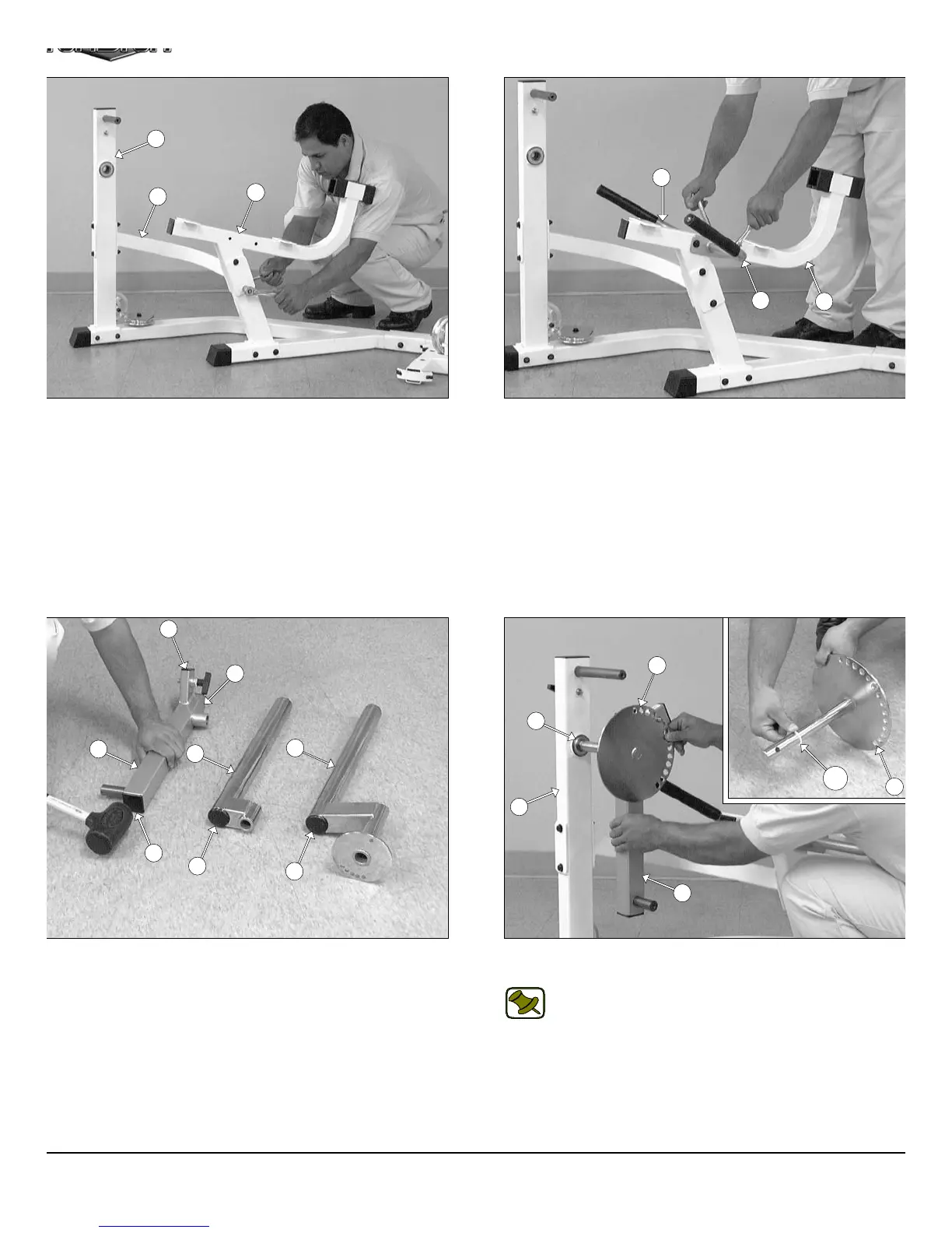
IG. 12 Next, attach the Leg Extension Arm Support (#13) to the
g Extension Front Frame (#11) using two Hex Head Cap Screws
8-16 X 4 1/4 (#104), four Flat Washers SAE 3/8” (#91), and two Nylon
sert Lock Nuts 3/8-16 (#100). Next, attach the other end of the Leg
xtension Arm Support (#13) to the Leg Extension Seat Frame
12) using two Hex Head Cap Screws 3/8-16 X 3 1/4 (#106), four Flat
ashers SAE 3/8” (#91), and two Nylon Insert Lock Nuts 3/8-16
100).
IG. 14 Using a rubber mallet, insert two Plastic Insert Caps 2” Sq.
85), and one Plastic Insert Cap 1 X 2 (#87) into the tube-ends of the
ivot-Arm (#25). Next, insert one Plastic Insert Cap 2” Rd. (#88) into
e tube-end of the Swivel Foam Roll Tube (#29), and the Top Adj.
g Hold-Down Tube (#32).
FIG. 13 Attach the Leg Extension Right Handle (#45) and the Le
Extension Left Handle (#46) to the Leg Extension Seat Frame (#12
in the position as shown above, using two Hex Head Cap Screws 3/
16 X 3 1/4 (#106), four Flat Washers SAE 3/8” (#91), and two Nyl
Insert Lock Nuts 3/8-16 (#100).
FIG. 15 Insert a Nylon Washer 1 X 1 1/4 (#122) to the Circul
Plate w/ Axle (#16) as shown in caption above.
Note: It is recommended to lubricate the axle on the Circul
Plate w/ Axle (#16) with multi-purpose grease prior
assembling.
Next, attach the Pivot-Arm (#25) to the Circular Plate w/ Axle (#16)
Then, insert the Circular Plate w/ Axle (#16) into the Ball Bearin
housing of the Leg Extension Front Frame (#11).
5
11
13
12
46
45
12
25
88
88
85
85
87
29
32
16
122
16
11
61
25
AP-250S_AP-250D Apollo 2-Stack Gym Syste