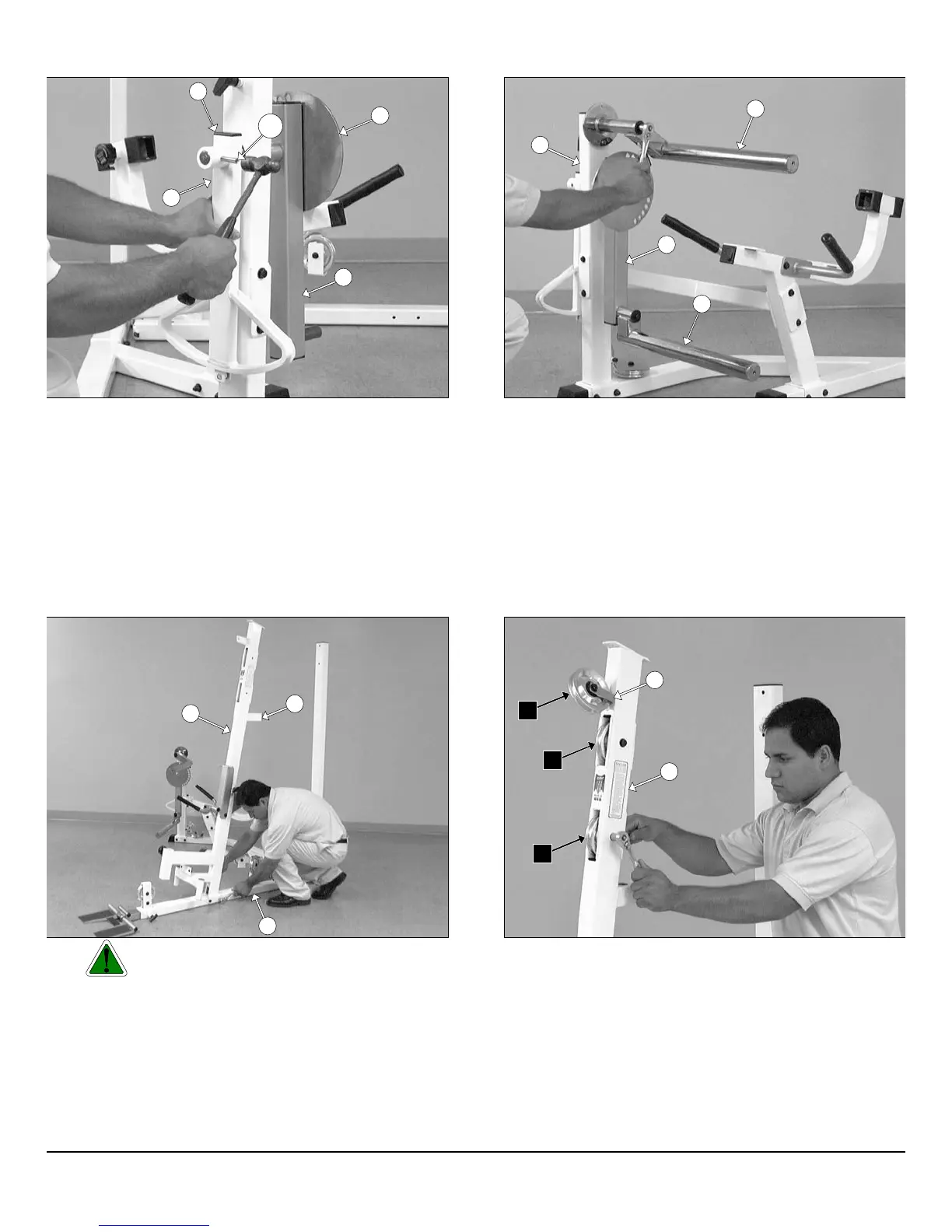
IG. 16 Attach the Actuator Arm (#43) to the axle of the Circular
late (#16). Next, align the hole of the Actuator Arm (#43) with the
le of the axle of the Circular Plate (#16) and, using a hammer, insert
e Roll Pin 3/8 X 1 1/2 (#123). Be sure that the Roll Pin 3/8 X 1 1/2
123) is aligned with the holes before hammering into place. In
dition, make sure the Roll Pin 3/8 X 1 1/2 (#123), after hammered in,
comes flush on both sides of the Actuator Arm (#43). Next, using a
bber mallet, insert one Plastic Insert Cap 1 X 2 (#87) into the tube-
dof the Actuator Arm (#43).
IG. 18 Caution: It is strongly recommended to use another
person in assisting with this assembly.
ttach the Front Frame (#3) to the Base Frame (#2) using two Hex
ead Cap Screws 3/8-16 X 4 1/4 (#104), four Flat Washers SAE
8” (#91) and two Nylon Insert Lock Nuts 3/8-16 (#100). Next, using a
bber mallet, insert one Plastic Insert Cap 2” Sq. (#85) into the tube-
d of the Front Frame (#3).
FIG. 17 Next, attach the Top Adjustable Leg Holder Tube (#32)
the Leg Extension Front Frame (#11) using one Hex Head Cap Scre
3/8-16 X 1 (#113), one Split Lock Washer 3/8” (#95), and one Fend
Washer 3/8 X 1 1/2 (#92). Next, attach the Swivel Foam Roll Tub
(#29) to the Pivot-Arm (#25) using one Hex Head Cap Screw 3/8-16
1 (#113), one Split Washer 3/8” (#95), and one Fender Washer 3/8 X
1/2 (#92).
FIG. 19 Next, attach one Pulley 4 1/2” Rd. (#68-Labeled C4), an
one Cable Retainer L-Shaped Bracket (#28), in the position as sho
above, to the plate of the Front Upright (#3) using one Hex Head Ca
Screw 3/8-16 X 1 3/4 (#110), two Flat Washers SAE 3/8” (#91), an
one Nylon Insert Jam Lock Nut 3/8-16 (#101). Next, attach two Pulle
4 1/2” Rd. (#68-Labeled C6,D7) to the pulley brackets of the Fro
Upright (#3) using two Hex Head Cap Screws 3/8-16 X 2 1/2 (#108
four Flat Washers SAE 3/8” (#91), and two Nylon Insert Jam Lock Nu
3/8-16 (#101).
6
wner
s
anua
:
ssem
y
nstruct
on
16
87
123
43
25
32
29
25
11
3
85
2
28
3
D7
C6
C4
P-250S_AP-250D Apollo 2-Stack Gym System