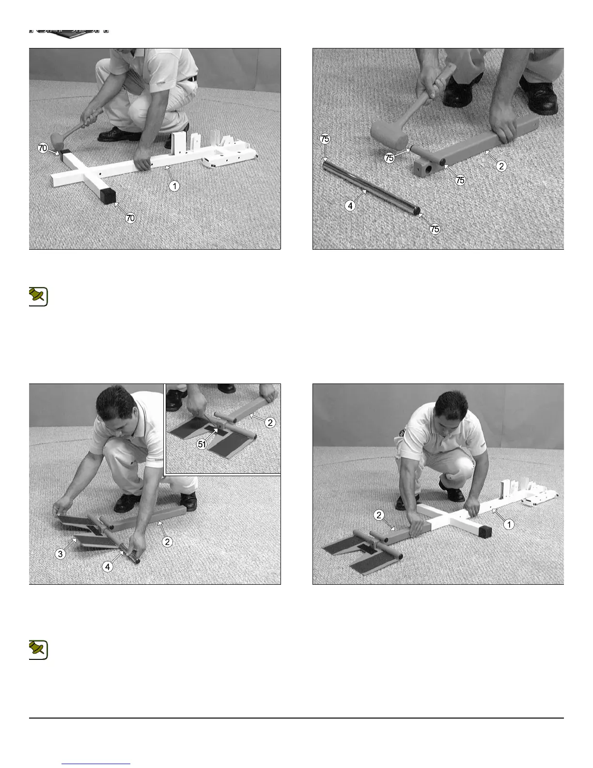
IG. 4 On a flat surface, lay the Base Frame (#1) down and insert two
lastic End Caps w/Groove 2” Sq. (#70) onto the tube-ends of the Base
rame (#1), as shown above.
Note: When positioning the Base Frame (#1) consider the
complete area surface of the TS-1000. Use the overhead view on
the cover page for designing your layout before assembling.
FIG. 5 Next, using a rubber mallet, insert four Plastic Insert Caps
Rd. (#75) into the four tube-ends of the Low Row Stabilizer (#2) and th
Foot Roll Tube 1 x 16 (#4).
IG. 6 Next, attach the Low Row Foot Support (#3) to the Low Row
tabilizer (#2) and secure it into place using one Foot Roll Tube 1 x 16
4). Using the supplied Hex Key 3/16” (#114), secure the Foot Roll
ube (#4) into place using one Set Screw 3/8-16 x 1/2 (#51), as shown in
ption above.
Note: Be sure the Foot Roll Tube (#4) is flush on each end after
inserted into the Low Row Foot Support (#3).
FIG. 7 Insert the Low Row Stabilizer (#4) into the receptacle on th
Base Frame (#1), as shown above.
3
TS-1000 Home Gym w/Adjustable High-Low Pulley Syste
NOTE:
NOTE: