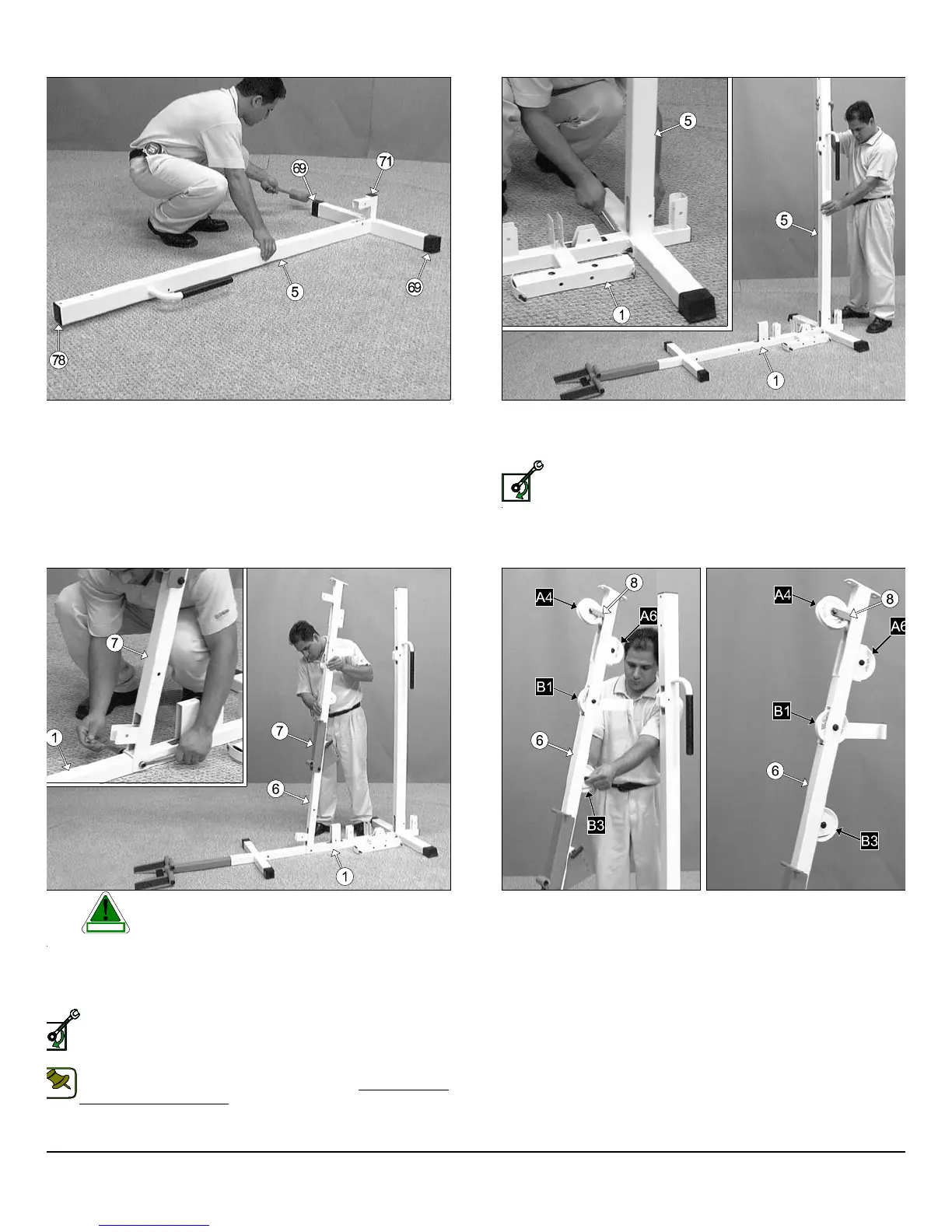
IG. 8 Locate the Rear Upright (#5), and using a rubber mallet insert
o Plastic End Caps w/Groove 2 x 3 (#69) onto the tube-ends of stabi-
er tube. Next insert a Plastic Insert Cap 2” Sq. (#71), and a Plastic In-
rt Cap 2 x 3 (#78) into the tube-ends, as shown above.
FIG. 9 Next, attach the Rear Upright (#5) to the Base Frame (#1) a
secure it into place using two Hex Head Cap Screws 3/8-16 x 4 (#98), fo
Flat Washers SAE 3/8” (#87), and two Nylon Insert Lock Nuts /38-1
(#92).
Loosely Fasten: Do not completely fasten this hardware asse
bly at this time, as it will be completely fastened later in the a
sembly process.
IG. 10 Caution: It is recommended to use another person in as-
sisting with this assembly.
ttach the Front Upright (#6) to the Base Frame (#1) and secure it into
lace using one Hex Head Cap Screw 3/8-16 x 2 3/4 (#100), two Flat
ashers SAE 3/8” (#87), and one Nylon Insert Jam Lock Nut 3/8-16
93).
Loosely Fasten: Do not completely fasten this hardware assem-
bly at this time, as it will be completely fastened later in the as-
sembly process.
Note:The black boxed letters pointing to the pulleys are used
throughout this manual as reference to the Cable Mapping
Diagram on pages 21-29. These black boxed letters will be
primarily used for locating certain pulleys during the cable routing
process beginning with Fig. 11.
FIG. 11 Affix a Nylon Pulley 4 1/2 Rd. (#67- Labeled A4) to the pulle
plate located on the Front Upright (#6) and secure it into place using on
Cable Retainer Bracket L-Shaped (#8), one Hex Head Cap Screw 3/
16 X 1 3/4 (#102), two Flat Washers SAE 3/8” (#87), and one Nylon Inse
Jam Lock Nut 3/8-16 (#93). Note: Be sure to position the Cable Retain
Bracket L-Shaped (#8) as shown above.
Next, attach two Nylon Pulleys 4 1/2 Rd. (#67-Labeled A6, B
into the pulley brackets located on the Front Upright (#6) and secu
them into place using two Hex Head Cap Screws 3/8-16 X 1 3/4 (#102
four Flat Washers SAE 3/8” (#87), and two Nylon Insert Jam Lock Nu
3/8-16 (#93). Next, insert a Nylon Pulley 4 1/2 Rd. (#67-Labeled B1) in
the Front Upright (#6) and secure it in place using one Hex Head Ca
Screw 3/8-16 X 2 1/2 (#10), two Flat Washers SAE 3/8” (#87), and on
Nylon Insert Jam Lock Nut 3/8-16 (#93).
S-1000 Home Gym w/Adjustable High-Low Pulley System 4
wner
s
anua
:
ssem
y
nstruct
on
CAUTION
SELY FASTEN
NOTE: