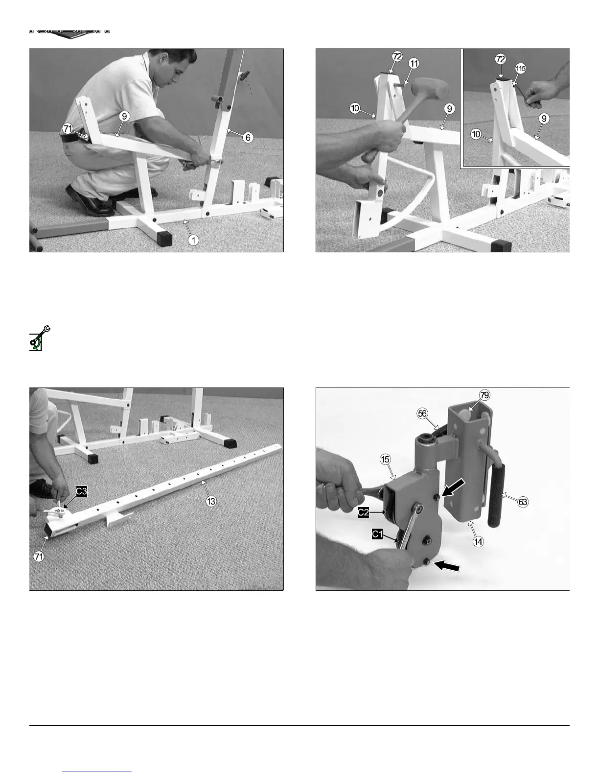
FIG. 13 Locate the Leg Extension Arm (#10), and using a rubber m
let, insert one Plastic Insert Cap 1 1/2 Sq. (#72) into the tube-end.
Affix the Leg Extension Arm (#10), in the position as sho
above, to the Leg Extension Bench Frame (#9) and secure it into pla
by inserting the Leg Extension Axle 1/2 X 2-3/4 (#11) through the Le
Extension Bench Frame (#9) and Leg Extension Arm (#10) until it b
comes flush with both sides of the Leg Extension Bench Frame (#9).
Next, secure the Leg Extension Axle 1/2 X 2-3/4 (#11) to th
Leg Extension Bench Frame (#9) using two Set Screws 1/4-20 X 3/
(#52), as shown above. Use the supplied Hex Key 1/8” (#115) f
fastening these Set Screws.
IG. 12 Attach the Leg Extension Bench Frame (#9) to the Base
rame (#1) and secure it into place using one Hex Head Cap Screw 3/8-
X 4 1/2 (#96), two Flat Washers SAE 3/8” (#87), and one Nylon Insert
m Lock Nut 3/8-16 (#93). Next, attach the Leg Extension Bench
rame (#9) to the Front Upright (#6) and secure it into place using one
ex Head Cap Screw 3/8-16 X 2 3/4 (#100), two Flat Washers SAE
8” (87), and one Nylon Insert Jam Lock Nut 3/8-16 (#93).
Loosely Fasten: Do not completely fasten this hardware
assembly at this time, as it will be completely fastened later in the
assembly process.
ext, using a rubber mallet, insert one Plastic Insert Cap 2” Sq. (#71) into
e front of the Leg Extension Bench Frame (#9).
IG. 14 Using a rubber mallet, insert a Plastic Insert Cap 2” Sq. (#71)
to the tube-end of the High-Low Selectorized Upright (#13). Next, in-
rt a Nylon Pulley 4-1/2 Rd. (#67-Labeled C#) into the pulley bracket of
e High-Low Selectorized Upright (#13) and secure it into place using
ne Hex Head Cap Screw 3/8-16 x 1 3/4 (#102), two Flat Washers SAE
8” (#87), and one Nylon Insert Jam Lock Nut 3/8-16 (#93)
FIG. 15 Insert the two Nylon Pulleys 3 1/2 Rd. (#68) into the High-Lo
Double Pulley Bracket (#15) and secure them into place using two H
Head Cap Screws 3/8-16 x 1 3/4 (#102), four Flat Washers SA
3/8” (#87), and two Nylon Insert Jam Lock Nuts 3/8-16 (#93). Next, a
semble two Hex Head Cap Screws 1/4-20 x 1 1/2 (#104), and two Nylo
Insert Lock Nuts 1/4-20 (#95) to the High-Low Double Pulley Brack
(#15), in the positions indicated by the black arrows.
5
TS-1000 Home Gym w/Adjustable High-Low Pulley Syste
SELY FASTEN