TUNGSTEN T series ATV winch
7
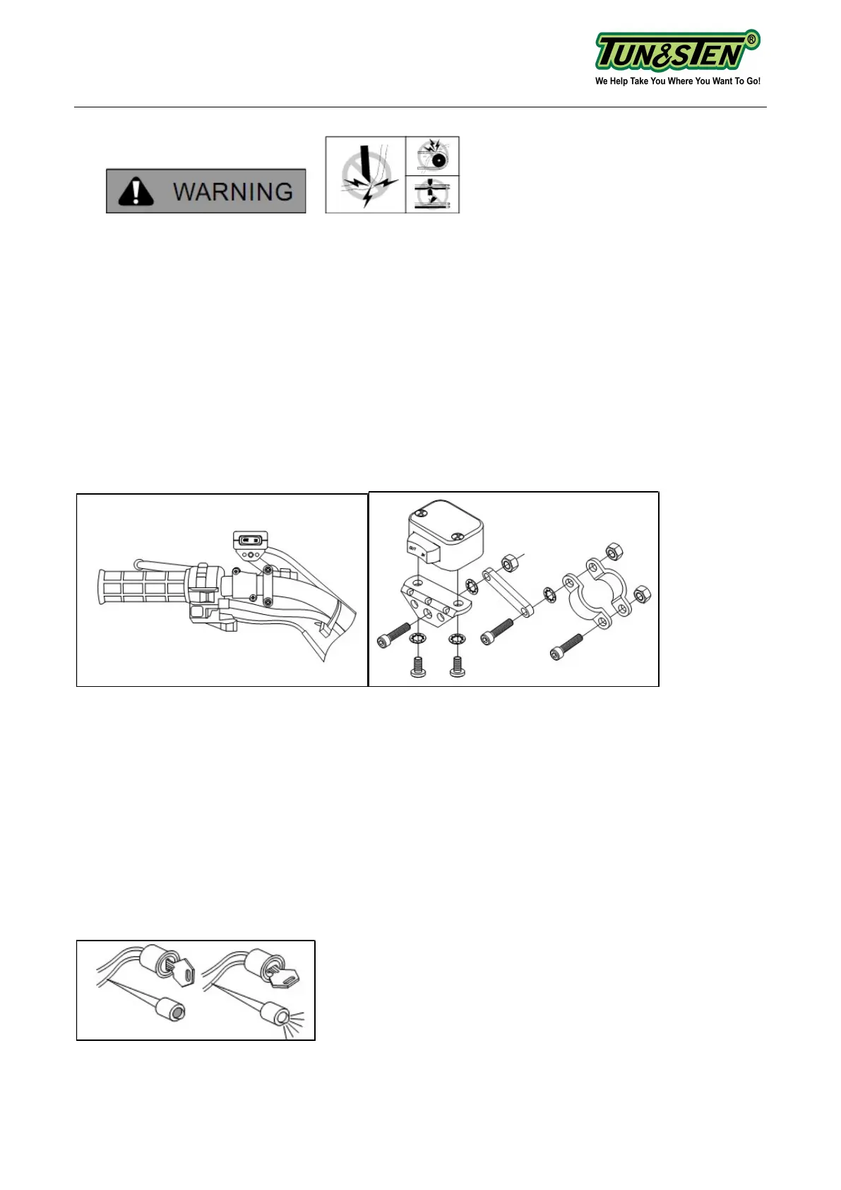
Step (3)- Mounting the Remote Control (Figure 4 -7)
TO PREVENT SERIOUS INJURY OR DEATH FROM ELECTRICAL FIRE:
• Do NOT route electrical cables across sharp edges.
• Do NOT route electrical cables through or near moving parts.
• Do NOT route electrical cables through or near any high heat parts.
• Avoid pinch and wear/abrasion points when installing all electrical cables.
TO AVOID INJURY AND PROPERTY DAMAGE:
• Use caution when moving or repositioning any vehicle controls so as to not compromise
the safe operation of the ATV. Select a mounting position that will provide clearance for all
vehicle controls.
• Before securing the switch cable with tie wraps, make sure that the handlebars have full
range of motion.
Figure 4: handlebar mount. Figure 5: Mini-rocker switch assembly
Exact positioning may vary depending on ATV make and model.
• It is recommended that the switch be installed on the left handlebar. A piece of electrical
tape around the handlebar will help prevent rotation of mount on the handle bar.
• Do NOT tighten over any hoses or cables.
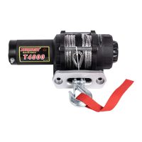
• Once the handle bar switch is mounted, route the two bullet terminal wires back to where
the contactor will be mounted. Splice the end of the red wire to a key controlled accessory
circuit of the ATV (use the provided wire splice). Using a test light (figure 6), locate a suitable
wire from the ATV key switch. The wire should only have power when the key is in the "ON"
position.
Figure 6: Use a test light to locate a suitable wire