4
INTRODUCTION
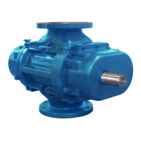
CONGRATULATIONS on your purchase of a new Qx
®
Rotary Positive Displacement Air Blower from Tuthill Vacuum & Blower
Systems. Please examine the blower for shipping damage, and if any damage is found, report it immediately to the carrier. If the
blower is to be installed at a later date make sure it is stored in a clean, dry location and rotated regularly. Make sure covers are kept
on all openings. If blower is stored outdoors be sure to protect it from weather and corrosion.
Qx blowers are built to exacting standards and if properly installed and maintained will provide many years of reliable service. We
urge you to take time to read and follow every step of these instructions when installing and maintaining your blower. We realize
getting any new piece of equipment up and running in as little time as possible is imperative to production, so we have tried to make
these instructions as straightforward as possible.
WARNING: Serious injury can result from operating or repairing this machine without first reading the service
manual and taking adequate safety precautions.
IMPORTANT: Record the blower model and serial number of your machine in the OPERATING DATA FORM on the inside back cover
of this manual. You will save time and expense by including this reference identification on any replacement part orders, or if you
require service or application assistance.
OPERATING CHARACTERISTICS
Q
x
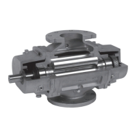
blowers are rotary positive displacement type units with tri-lobe rotors rotating in opposite directions within a housing closed at
the ends by end plates. The pumping capacity is determined by size, operating speed, and differential pressure conditions.
Effective sealing of the inlet to the discharge is accomplished through the use of very small operating clearances. The resulting
absence of moving contact eliminates the need for any internal lubrication. Clearances between the rotors during rotation are
maintained by a pair of accurately machined helical timing gears, mounted on the two shafts extended outside the air chamber. The
two intermeshing rotary lobes are designed to rotate and trap air or gas between each rotor and the housing. As the rotor lobes
rotate past the edge of the suction port, the trapped air or gas is essentially at suction pressure and temperature. Since the blower is
a constant volume device, the trapped air remains at suction pressure until the leading rotor lobe opens into the discharge port. The
close clearances between the rotors inhibit back slippage of the trapped volume from between the rotors and the trapped volume is
forced into the discharge piping. Compression occurs not internal to the blower, but by the amount of restriction, either downstream
ot the blower discharge port, or upstream of the blower inlet port.
Air moves not between the rotors but between the rotors and the side of the housing. Also, the machine is bi-directional, meaning that
the direction of rotation of the blower can make either side the inlet or discharge. See also Figure 1, Flow Direction by Rotation.
Blowers must be protected by cut-in switches or with bypass valving to limit differential pressure across the blower. This is described
in greater detail in the Operating Limitations section, below. When a belt drive is employed blower speed can usually be adjusted
to obtain desired capacity by changing the diameter of one or both sheaves, or by using a vari-speed motor pulley.
OPERATING LIMITATIONS
To permit continued satisfactory performance, a blower must be operated within certain conditions. The manufacturer’s warranty
is contingent on such operation. Maximum limits for temperature and speed are specified here for various blower sizes when
operated under the standard atmospheric conditions. Do not exceed these limits.
EXAMPLE: Seldom does the operation of a blower result in pressure differentials large enough to strain the blower drive train
(bearings, gears, and seals). Typically, the maximum allowable temperature limit (the limit is a function of the temperature rise as
well as the inlet temperature), for any particular blower may occur well before the maximum speed or allowable power rating is
reached. Temperature rise then becomes the limiting condition. The operating limit is to be determined by the maximum rating
reached first, and it can be any one of the three: temperature, speed, or horsepower.
NOTE: Specially ordered blowers with non-standard construction, or with rotor end clearances greater than shown in this manual,
will not have the operating limits specified here. Contact your Tuthill Vacuum & Blower Systems sales representative for specific
information.
 Loading...