19
Wiring Instructions
Cable Marking Explanation
X-axis Endstop Switch Cable
X (4-PIN) → X-axis Stepper Motor Cable
Y (3PIN) → Y-axis Endstop Switch Cable
Y (4-PIN) → Y-axis Stepper Motor Cable
Z (2-PIN) → Z-axis Endstop Switch Cable
Z (4-PIN) → Z-axis Stepper Motor Cable
A (2-PIN) → Laser Signal Cable
E (3-PIN) → Flame Detector Signal Cable
1 (2-PIN) → Laser Fan Line
Note: The term "PIN" denotes the number of pins in the cable connector.
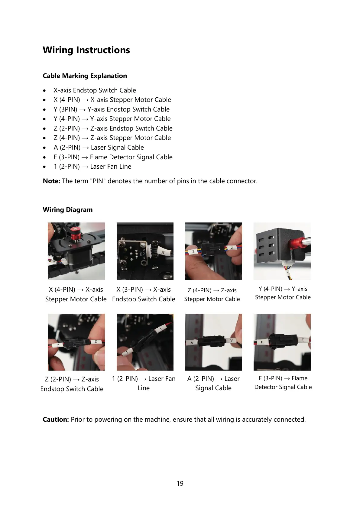
Wiring Diagram
Caution: Prior to powering on the machine, ensure that all wiring is accurately connected.
X (4-PIN) → X-axis
Stepper Motor Cable
X (3-PIN) → X-axis
Endstop Switch Cable
Z (4-PIN) → Z-axis
Stepper Motor Cable
Y (4-PIN) → Y-axis
Stepper Motor Cable
Z (2-PIN) → Z-axis
Endstop Switch Cable
1 (2-PIN) → Laser Fan
Line
A (2-PIN) → Laser
Signal Cable
E (3-PIN) → Flame
Detector Signal Cable