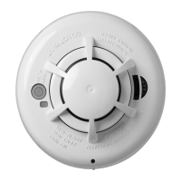
Residential - Allows connection of conventional 2-wire smoke detectors and clean contact devices.
Open circuit is defect. Short circuit is an instant alarm if using programmable “MCP” facility.
(N/C contacts require PA0443 Contact conversion module).
Default configuration: “MCP” option disabled and smoke detectors Non-Brigade signalling, Non-Bell
ringing, Non-Indicating, AVF enabled.
The default configuration for “MCP” (if enabled): Latching, Brigade signalling, and Bell ringing.
A Residential circuit will latch a smoke detector activation in alarm for a per-board programmable period
(0-250 sec, default 30 sec, 0 = stay latched) before attempting to self-reset. This allows local sounders
to operate for the length of the delay per detector activation.
Smoke and thermal/MCP activations can be mapped separately to ancillaries, brigade, and bells.
Open circuit MCP alarm cannot be allowed on Residential circuits (i.e. combined operation) because
once a smoke detector had operated, an open circuit beyond the operated detector would not be able
to be detected. A contact conversion module (PA0443) is therefore required for MCPs.
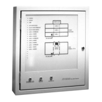
7-Segment Displays - There are three 7-segment displays per board. See “Display Codes” later.
Zone Index LEDs - Single flash = thermal/manual alarm. Double flash = smoke alarm. The Normal LED
has a power-save cadence when mains is off.
Buzzer - The buzzer generally indicates the presence of abnormal conditions when the door is closed,
and the presence of defects when the system is not remotely connected.
Evacuation Switch - The Evacuation key switch allows manual activation of the alerting devices (without
calling the Brigade). It may also be programmed to activate ancillary outputs.
Silence Alarms Switch - Operation of the Silence Alarms switches (external or internal) prevents the
alerting devices sounding when an alarm is present. They may also be programmed to de-activate
ancillary outputs. The external keyswitch generates a defect.
Note: These switches will not silence the alerting devices for an Evacuation Control circuit alarm or the
ERD- input.
Services Restore Switch - The Services Restore switch is intended to allow the Brigade to restore
ancillary services even when an alarm is present. The effect of this switch on the ancillary outputs is
programmable.
Mains Switch - 230V Mains isolation is provided by a switch on the mains termination cover.
Brigade Interface - Fit a 2W/4W General Purpose SGD (PA0862), or a General Purpose Brigade Relay
Interface (PA0861). These boards mount on stand-offs and plug into the ”Brigade Signalling Interface”
Connector (J20) (Master board only). If an interface is not fitted, select “Local” mode (Lo) in programming.
RZDU Interface - Up to 8 compatible Remote Zone Display devices can be connected to the Master
board. Wiring is a 3 or 4-core star-spur arrangement. Refer to the Technical Manual for further details.
Brigade control switches and a Brigade index may be provided at each RZDU.
Page 2 4 July 2003 LT0312 v1.03