T1200
MARINEC-P-A
3 02/14
PAGE 40 of 67
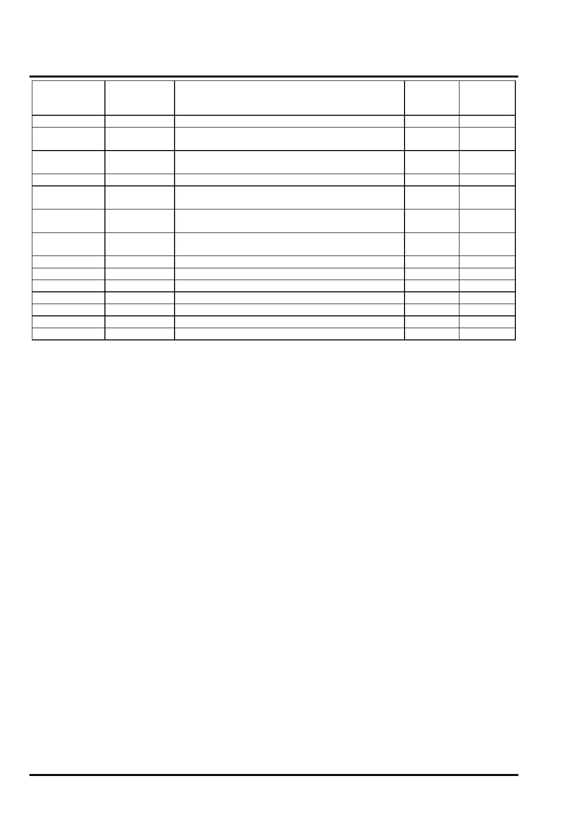
Manufacturer Part no. Description
Current
Devices
Conventional Enhanced CO Detector [marine]
Tyco 601H-R-M
Conventional Heat Detector
(Rate of Rise) [marine]
0.067 17
Tyco 601H-F-M
Conventional Heat Detector
Fixed Temperature {60 Deg C) [marine]
0.067 17
Conventional Optical Smoke Detector [marine]
Tyco 601PH-M
Conventional High Performance Optical Smoke
Detector [marine]
0.067 17
Non Branded 611H-F
Conventional Heat Detector
Fixed Temperature (60 Deg C)
0.067 17
Non Branded 631H-F
Conventional Heat Detector
Fixed Temperature (90 Deg C)
0.067 17
Manual Call Point [Marine]
Manual Call Point [Marine]
Notes:
1. These panels are designed with resistors as end of line devices. In order for detector head removal
monitoring to function correctly any line continuity diodes in the detector bases that are in circuit when
the detector head is removed must be disconnected. Removal of a detector will result in an open-circuit
fault and any devices further along the zone wiring will no longer function.
2. The total current drawn by detectors on a zone must not exceed 1.2mA, otherwise the panel may not
detect an open circuit fault on the zone wiring. The above table shows the AVERAGE standby current
drawn by each device. To calculate the total number of devices that may be connected to a zone, add
up the individual standby current values for each device and make sure that the total current does not
exceed 1.2mA.
3. If a galvanic isolator (MTL5061/MTL5561) is used on the zone then this device will also draw current.
Allow at least 0.1mA for the barrier (this could rise to 0.4mA depending on how much current is drawn
by the detectors).
4. The maximum number of devices per zone including manual call points must not exceed 32 even if the
current consumption is less than 1.2mA. This is a requirement of BSEN54 which requires that a single
fault on a zone should not prevent the operation of more than 32 devices.
The values in the above table are for guidance only and will vary for individual detectors. Each zone should be
fully checked for correct fault monitoring during installation & commissioning.
 Loading...

